Search results
Query: circuit
Links: 338 | Categories: 14
Categories
- Software > Circuit Design
- Technical Reference > Batteries
- Technical Reference > Batteries > Battery Charger
- Technical Reference > Electronics
- Manufacturers > Test Equipment > Impedance Analyzers
- Technical Reference > Morse Code Oscillator
- Technical Reference > Test Equipment > Multimeter
- Software > PCB Design
- Technical Reference > Receiver Front-End Protector
- Software > RF Design
- Technical Reference > Soldering and Desoldering
- Technical Reference > Transverters
- Technical Reference > Vacuum tube
- Software > Vector Network Analyzer
-
 A workbench instrument capable of testing transistors, diodes, FETs, usefull constructing QRP circuitry.
 -
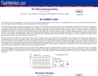 The use of dummy load is mandatory for off-air adjustment of the transmitters. Build one.
 -
 This circuit came out of some work done for two antenna analysers
 -
 TSC International produces soft magnetic sheet steel, custom-stamped and heat-treated to achieve optimal electrical characteristics for applications such as motors, generators, linear power supplies, and ballasts. The company's manufacturing process focuses on precise material engineering to meet specific performance requirements in various electrical systems. They also specialize in soft magnetic core materials essential for transformers, chokes, and inductors. These core materials are utilized in power supplies, lighting ballasts, signal conditioning circuits, inverters, and battery chargers, providing critical magnetic properties for efficient energy conversion and signal integrity. Located at 39105 Magnetics Blvd, Wadsworth, IL 60083-0399, TSC International provides contact via sales@tscinternational.com or phone at +1 (0) 847 249 4900, facilitating direct inquiries regarding their magnetic component offerings.
 -
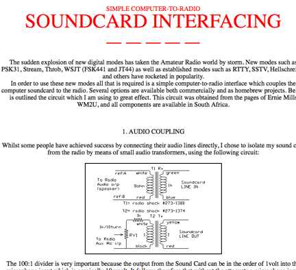 Homebrew your PC sound card to radio interface with this circuit obtained from the pages of Ernie Mills WM2U.
 -
 KB22UT Article on how protecting ham radio station and in particular I/O Lines such as AC power, coax cable, control circuits, telephone line.
 -
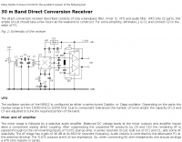 The direct conversion receiver described consists of only a bandpass filter, mixer IC, VFO and audio filter. With only 22 parts, this simple circuit should take a few hours at the weekend to construct.
 -
 Mark Connelly, WA1ION article on Medium Frequency Amplifier Circuits in PDF format, include some RF amplifier schematics
 -
 Demonstrates a range of specialized radio frequency equipment and consulting services for amateur and professional applications. The offerings include _Vector-Finder_ direction finding antennas, various test equipment such as _gate dip meters_ and RF sniffers, and communications receiving adjuncts. Additionally, the company produces satellite antennas for weather satellite reception, voice amplification devices like the _Flex-Mike_, and custom prototype circuit boards. The company's product line addresses needs for precise RF measurement, signal detection, and specialized antenna systems, particularly for direction finding and satellite communications. Their historical association with National Radio (HRO) suggests a legacy in radio technology. The site also highlights a subsidiary, Sierra Mountain Products, which offers outdoor recreational gear, indicating a diversification beyond core RF manufacturing.
 -
 A vertical antenna project for the 7MHz made with some spare parts. Based on a broken 20 foot fishing pole, it is based on a good ground system made with radials and a capacitive hat done to increase the global radiation resistance of the antenna. A custom loading coil is also included in this project to perfectly tune the antenna to the CW portion of the 40 meters band.
 -
 This test circuit is easy to duplicate, and demonstrates the extreme voltages that appear in an amplifier when the load is improper for the amount of drive power applied.
 -
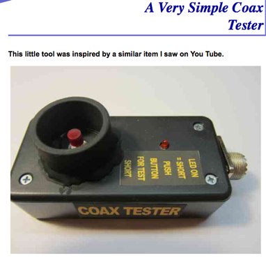 This useful coax tester allows you to screw the PL-259 onto the tester to get a GO/NO GO status. When the LED lights up- you have a short circuit.
 -
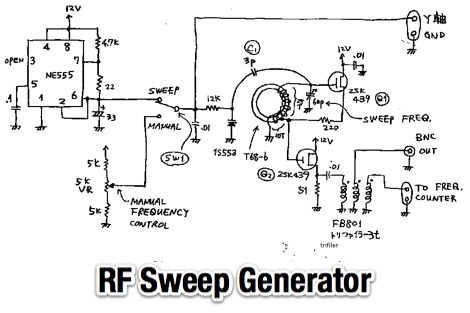 A simple RF sweep generator circuit diagram by JF1OZL
 -
 Around 200 electronic circuits in pdf format or images, There are also over 1000 links to useful electronics, freeware, open source websites. There are some 100 useful documents, software and pcbs too. Mainly industrial electronics, instrumentation. Covers Various aspects of electronics and basics of circuit design.
 -
 Key facts about how to solder, how to solder wire, how to solder pcb's, and including general soldering techniques and the best ways of making good solder joints for electronic circuits and construction. Includes video
 -
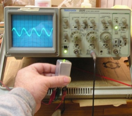
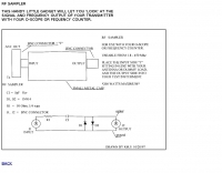 This circuit will let you look at the signal and frequency output of your transceiver.
 -
 Constructing a high-power 70cm solid-state amplifier presents unique challenges, particularly when aiming for 500 watts output using modern LDMOS devices. This resource details the author's experience building a 70cm amplifier based on a _Freescale MRFE6VP5600H_ transistor, initially from an RFHAM kit. It meticulously outlines the necessary modifications to achieve advertised performance, including optimizing input and output matching, correcting bias circuitry, and ensuring proper output balun connections for stability. The author shares specific adjustments, such as trimming the prototyping board for better transistor fit, drilling additional mounting holes for improved heat sinking, and replacing original matching capacitors with a single _20pf MIN02 metal mica_ for superior output. A critical fix involved jumpering gate decoupling pads to balance the push-pull transistor halves, which increased output to 580W and improved IMD. The resource also highlights a crucial correction to the output balun connection, initially reversed in the _Dubus_ article schematic, which resolved intermittent stability issues. Test results are provided, showing input power, output power, and drain current at 50V, demonstrating the amplifier's performance after modifications. This practical account offers valuable insights for hams undertaking similar high-power UHF amplifier projects, especially those working with LDMOS devices and kit-based constructions.
 -
 A DIY Automatic Band Decoder (ABD) project, designed for dual-radio operation, addresses the common challenge of integrating band data with older transceivers lacking dedicated outputs. This particular build utilizes an AVR AT90S8515 microcontroller and a 16x2 Liquid Crystal Display (LCD) to provide band information, specifically targeting Kenwood rigs via a computer's LPT port. The design aims for cost-effectiveness while maintaining functionality, offering a solution for hams seeking to add automatic band switching capabilities to their station without significant expense. The project outlines the core components required, including the microcontroller, LCD, and an enclosure, noting that the Printed Circuit Board (PCB) fabrication and AVR programming might present challenges for some builders. It details the input requirements, such as a four-pin input and PTT for each radio, along with a 13.8V DC power supply. The decoder provides 2x6 outputs capable of sinking 500mA, suitable for controlling external devices like antenna switches or filters. Despite the original unit being damaged by a lightning strike in 2004, the author confirms its successful operation prior to the incident and mentions plans for a revised version. The resource includes a schematic in PDF format and images of the finished PCB and assembled unit, demonstrating the practical implementation of the design.
 -
 A simple free running oscillator oscillating at the receiver\'s IF (intermediate frequency) beats with the incoming signals in either CW or SSB and the resultant audio frequency goes to the AF amplifier.
 -
 Details the construction of an **HF converter** designed by M1GEO, George Smart, specifically to extend the frequency range of the FunCube Dongle Pro (FCD) for amateur radio reception. The FCD natively covers 64 to 1,700 MHz, but this project enables reception from 0 Hz to 64 MHz by up-converting signals to the FCD's operational range. It employs a **double-balanced mixer** with a 100 MHz local oscillator (LO) to translate incoming HF signals; for instance, a 1 MHz signal appears at 101 MHz within the FCD's passband. The design incorporates a 7th-order Chebyshev low-pass filter with a 62 MHz cutoff frequency at the input to mitigate image frequencies, ensuring cleaner spectral presentation. George provides the schematic, PCB masks, and Gerber files for replication, noting that Far Circuits also offers PCBs. The resource includes test results for the low-pass filter and measurements of LO leakage, identifying -36.8 dBm at 100 MHz as a potential sensitivity concern. M1GEO discusses potential improvements, such as adjusting the mixer's LO drive, adding a balance pot, or incorporating a post-mixer high-pass filter to reduce LO breakthrough. Audio recordings from 40m and 17m demonstrate the converter's performance with WRplus SDR software.
 -
 The m0xpd keyer project utilizes a PIC16F628A microcontroller, offering Iambic A and B modes, adjustable speed from 5 to 40 WPM, and variable weight control. It incorporates a sidetone generator with adjustable frequency and volume, along with a PTT output for transceiver control. The design includes a 16-pin DIL IC socket for the PIC, a 3.5mm stereo jack for the paddle, and a 3.5mm mono jack for the PTT output. Powering the keyer requires a 9V DC supply, which is regulated down to 5V for the PIC. The circuit board layout is designed for through-hole components, facilitating home construction. A detailed schematic and a parts list are provided, guiding builders through the assembly process. The project also discusses the firmware programming for the PIC16F628A, essential for the keyer's functionality. Construction details cover component placement and wiring, ensuring proper operation. The keyer's compact size makes it suitable for portable or shack use, providing a reliable CW interface.
 -
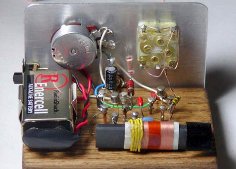 Collection of several Crystal Radio receiver circuits with schematics diagrams and pictures
 -
 Signal source circuit for 2.4 GHz by sv1bsx
 -
 This video will provide a foundation for understanding how power amplifier circuits work. If you are new to High Frequency Power Amplifier Circuit Design, this is the place to start.
 -
 Sunstone Circuits is your easiest source for quoting and ordering printed circuit boards online. We are three respected brands in one: PCBexpress quickturn boards, PCBpro.com full-featured and design-checked boards, and PCB123 design software.
 -
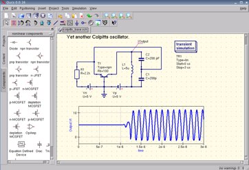
 Originally eveloped by I1FLC, uses seven plug in coils covering 3.0 to 30Mhz in a Colpitts oscillator circuit.
 -
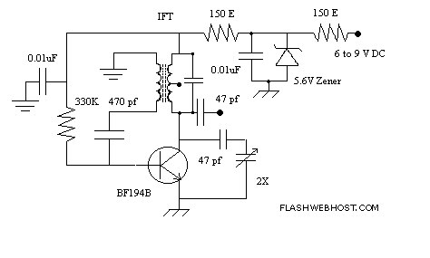
 A RF Probe circuit for the RADIO frequency experimenter to check the presence of a RF signal and also to measure its strength
 -
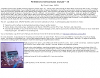
 The _Sci.Electronics FAQ: Repair: RFI/EMI Info_ document, authored by Daniel 9V1ZV, provides a detailed analysis of computer-generated RFI/EMI, focusing on its impact on radio reception. It identifies common RFI sources such as CPU clock rates (e.g., 4.77 MHz to 80 MHz), video card oscillators (e.g., 14.316 MHz), and even keyboard microprocessors, all of which generate square-wave harmonics across HF and L-VHF regions. The resource outlines a systematic procedure for pinpointing RFI origins, including disconnecting peripherals and using a portable AM/SW receiver with a ferrite rod antenna to localize strong interference sources. The document categorizes RFI mitigation into shielding, filtering, and design problems, offering practical solutions for each. It recommends applying conductive sprays like _EMI-LAC_ or _EMV-LACK_ to plastic casings of radios, monitors, and CPUs to create effective Faraday cages, emphasizing proper grounding and avoiding short circuits. For filtering, the guide suggests using line filters, ferrite beads, and toroids on power and data lines, and small value capacitors (e.g., 0.01 uF for serial/parallel, 100 pF for video) to shunt RFI to ground. It also discusses the use of bandpass, high-pass, low-pass, and notch filters on the receiver front-end or antenna feed to combat specific in-band noise.
 -
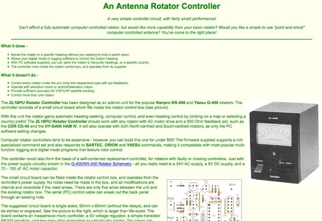 The ZL1BPU Rotator Controller has been designed as an add-on unit for the popular Kenpro KR-400 and Yaesu G-400 rotators. The controller consists of a small circuit board which fits inside the rotator control box
 -
 Modification leaves nearly all of the existing Omni agc circuitry intact, simply add an audio detector which modifies the delay characteristics of the original system by G3IXQ
 -
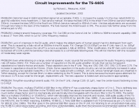 The page provides circuit improvements for the Kenwood TS-440S transceiver, addressing issues such as distortion in SSB signals, limited transmit frequency coverage, lack of crispness in RX audio, and flat audio response. The fixes include adjusting bias, cutting specific components, and changing capacitors to improve performance.
 -
 This online project guide details the construction of a homebrew boom microphone system. It details the assembly of a microphone shell from a 3/4" PVC pipe section and an end cap, requiring a drilled hole for a snug fit of the electret or condenser mic element. The internal wiring schematic specifies a **2.2 K** resistor and a **47 uF** polar capacitor for signal conditioning, with a circuit diagram provided for integration with IC-706 series transceivers. The guide outlines the use of CAT-5 cable for internal connections, incorporating strain relief at the rear of the mic shell, and an inline 3.5 mm jack to facilitate an external _PTT_ line, designed for a foot-mounted switch. Further construction involves fabricating a microphone shock mount from a 2-inch PVC connector, detailing the creation of four "fingers" and the insertion of screw-eyes for attaching elastic bands, which are twisted 180 degrees for tensioning and vibration isolation. A foam wind screen is also incorporated into the microphone assembly, secured with adhesive. The boom arm itself is repurposed from an articulated architect lamp, with the original lamp assembly converted into a **60 watt** resistive load for testing power sources. Microphone cabling is secured to the boom arm using wire ties, ensuring sufficient slack at hinge points to maintain articulation. The boom base is mounted to a bookshelf, requiring specific positioning to achieve proper microphone placement in front of the operator. Performance evaluation of the microphone system is conducted through on-air audio signal reports from other amateur radio operators. DXZone Focus: Online Project Guide | Boom Microphone Construction | Electret Mic Element | PTT Line
 -
 Provider of electronic components documentation. Offer a reliable tool to find semiconductors components technical information like parts, datasheets, cross reference, obsolete and new circuits.
 -
 An easy to build and extremely high performance antenna, works perfectly on all HF bands 3.5-28 MHz with some compromises, it is basically an half wave dipole for 40-80 meters, an LC circuit or trap 40 meters allows you to use a single radiating element.
 -
 137.7 kHz QRSS beacon exciter is described, utilizing a single chip for operation on the 2200m amateur band. The design focuses on simplicity and efficiency for weak signal applications, providing a compact solution for generating QRSS signals. This project targets the DX portion of the band, enabling long-distance communication with minimal power output. The resource details the construction and functionality of the **QRSS beacon**, emphasizing its **low-power operation** and suitability for experimental amateur radio. It provides insights into the circuit's architecture and potential for integration into existing station setups. The design aims to offer a practical and accessible entry point for amateurs interested in weak signal modes on the LF/MF bands.
 -
 Christoph Petermann DF9CY DRM demonstration receiver project including Circuit Diagram and component list
 -
 This circuit is very simple and has a fantastic range of potential uses.
 -
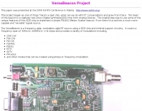 The VersaBeacon is a frequency agile, modulation agile RF source using a DDS chip and minimal support circuitry. It covers a frequency span of 1MHz to 150MHz in 1 Hz steps and provides a variety of modulations
 -
 A synthesized 2.3 GHz Amateur Television (ATV) transmitter design, conceived by Ian G6TVJ, is presented, targeting broadcast-quality video performance on the 13cm band and extending up to 2.6 GHz. The core of the design utilizes a commercial Z-comm Voltage Controlled Oscillator (VCO) that tunes from 2.2-2.7 GHz, providing a +10 dBm output and simplifying RF alignment. This VCO's stability, originally intended for narrowband applications, readily accepts high-frequency video modulation, contributing to the transmitter's robust performance. The exciter stage, incorporating a Mini Circuits VNA 25 MMIC amplifier, boosts the signal to +16dBm, while a Plessey SP4982 prescaler divides the output frequency for the synthesizer. The synthesizer employs a Motorola MC145151 CMOS parallel IC, favored over the common Plessey SP5060 for its superior video modulation characteristics and ease of programming without microprocessors. This choice addresses issues like LF tilt and distorted field syncs often seen with SP5060 designs, particularly when operating through repeaters or over long distances. The MC145151 divides the signal further, enabling precise frequency stepping, with programming handled by EPROMs for channel selection and LED display. The loop filter network, critical for video integrity, was developed through experimentation to prevent the PLL from reacting to video modulation, ensuring a clean transmitted picture. The transmitter incorporates a Down East Microwave commercial power amplifier module, delivering approximately 1.6W output, driven by the exciter through a 3dB attenuator. Construction involves surface-mount SHF components on micro-strip lines etched onto double-sided fiberglass board, housed within a tinplate box. The design boasts no AC coupling in the video path, preserving low-frequency response, a common failing in other ATV transmitters. Performance tests with a 50Hz square wave revealed no LF distortion, and a calibrated "Pulse & Bar" signal showed a near 100% HF response, demonstrating its capability for high-quality ATV transmissions.
 -
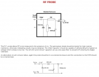 This RF probe circuit allows RF to be measured in the presence of DC
 -
 The CAT and audio interface version 3 project by PA5CA presents a comprehensive solution for integrating amateur radio transceivers with computer sound cards, facilitating digital mode operation and CAT control. It includes detailed schematics for the interface circuitry, illustrating the isolation transformers for audio paths and optocouplers for CAT data lines, ensuring robust electrical separation between radio and PC. The resource also provides PCB layouts, enabling constructors to fabricate their own boards for this specific design. The project outlines the component selection and assembly process, emphasizing the use of readily available parts to build a reliable interface. It addresses common challenges in sound card interfacing, such as ground loops and RF interference, through its isolated design. This construction guide offers practical insights into building a functional interface, making it suitable for hams interested in DIY radio accessories for digital modes like FT8, RTTY, and PSK31.
 -
 RF/Microwave Simulator for Puppy Linux by WN2A
 -
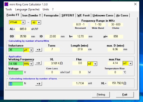 The program can be used to calculate inductors (coils) and their number of turns on ferrite cores, ferrite shells and air coils. These can be used for baluns, Ununs, bandpass filters, low pass filters, resonant circuits, and more. The technical specifications of the cores are already integrated in the program. Application is free and runs on Windows 32 bit versions only. To make it run on Windows 10 64 bit need to be unzipped in a single folder.
 -
 While intended mainly for antenna loading coils, this article also applies to other resonant systems, such as amplifier tank circuits.
 -
 Build you own RF probe, measure the level of RF voltage present at a particular point.
 -
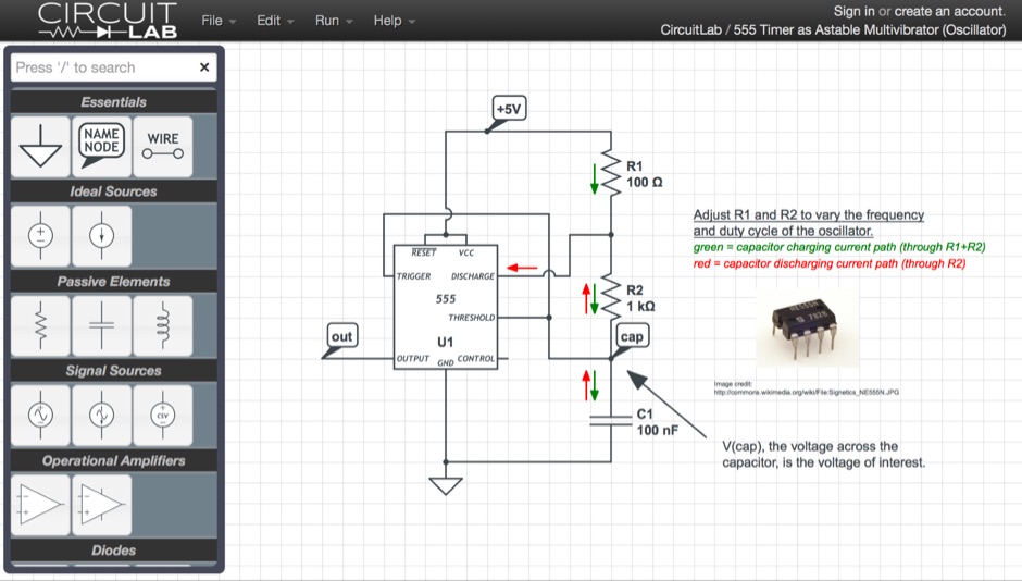 A browser based circuit simulator offering a large set of functionalities allowing to share and discuss designs
 -
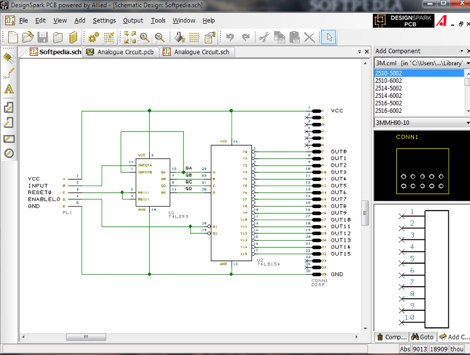 DesignSpark PCB is the world's most accessible electronics design software, specially designed for Rapid Prototyping and turning your circuit ideas into testable boards faster. Easy to learn and easy to use, DesignSpark PCB is free and can you can download DesignSpark from this site.
 -
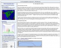 Some test circuits using the ACE-HF System Simulation & Visualization software, about reciprocal propagation on HF bands by NW7US
 -
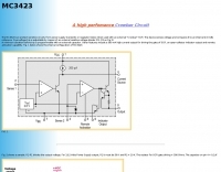 The MC3423 can protect sensitive circuity from power supply transients or regulator failure when used with an external "Crowbar" SCR.
 -
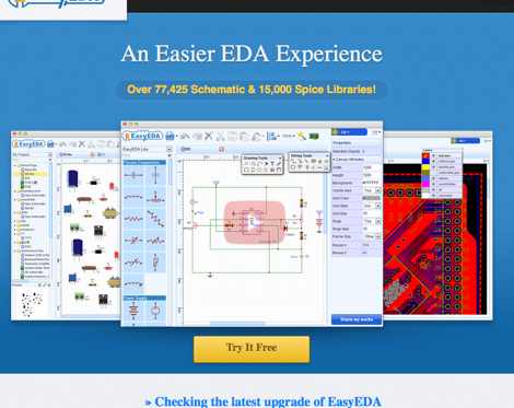 EasyEDA - Web-Based EDA, schematic capture, spice circuit simulation and PCB layout Online.