Search results
Query: Antenna
Links: 2831 | Categories: 173
This query is too generic. Please try adding an additional term to focus your research.
Categories
- Antennas > 20M > 20 meter Dipole Antennas
- Antennas > 20M > 20 meter Vertical Antennas
- Antennas > 20M > 20 meter Yagi antennas
- Antennas > 40M > 40 meter Delta Loop Antennas
- Antennas > 40M > 40 meter Dipole Antennas
- Antennas > 40M > 40 meter Loop Antennas
- Antennas > 40M > 40 meter Magnetic Loop Antennas
- Antennas > 40M > 40 meter Vertical Antennas
- Antennas > 40M > 40 meter Yagi Antennas
- Antennas > 6M > 6 meter J-Pole Antenna
- Antennas > 6M > 6 meter Moxon Antennas
- Antennas > 6M > 6 meter Yagi Antennas
- Manufacturers > Antennas > HF > Active antennas
- Software > Antenna analysis
- Manufacturers > Antenna Analyzers
- Radio Equipment > Antenna Analyzers
- Antennas > Antenna Books
- Antennas > Antenna Calculators
- Antennas > Theory > Antenna Gain
- Technical Reference > Antenna Launcher
- Manufacturers > Antenna Launcher
- Manufacturers > Antenna Masts and Mounts
- Shopping and Services > Antenna Mount
- Manufacturers > Antenna Parts
- Shopping and Services > Antenna Parts
- Technical Reference > Antenna Rotator
- Manufacturers > Antenna Rotators
- Software > Antenna rotor control
- Technical Reference > Antenna Switch
- Manufacturers > Antenna Switches
-
 Extended Double Zepp measurements for all ham bands, and online calculator. The antenna is constructed much like an ordinary Dipole antenna but with 5/8 Wavelength Elements matched with an added Impedance Matching Section of balanced feed line
 -
 Transformers can be used as part of a hybrid combiner or as phase inverters for an RX antenna array.
 -
 Some useful information for tuning mobile antennas gained the hard way. A collection of useful tips and hints on adjusting and matching a mobile antenna and methods of feeding a mobile antenna
 -
 Online antenna calculator for the microvert capacitive antenna
 -
 This is a remote antenna switch I use in my attic to connect transceivers in the basement to multiple antennas in the attic. The goal of this project is to be able to remotely connect one of the antennas in the attic to the only antenna cable available.
 -
 An Inverted-L with its long leg sloping to the ground. It will still work very good, even if the horizontal wire has to be sloped diagonally to the ground, as long as you have enough horizontal space to keep it at about a 45 degree angle or more from the pole.
 -
 This page presents an online calculator tool for determining the dimensions of various HF wire antennas operating between 1.8-30 MHz. Users input their desired resonant frequency to obtain precise measurements for four popular antenna types: standard flat-top dipole, inverted Vee, quad loop, and equilateral delta loop. The calculator provides comprehensive measurements including leg lengths, minimum heights, horizontal spreads, and feedpoint distances. Accompanying the calculator are detailed technical explanations, construction notes, and installation guidelines for each antenna type, making it a practical resource for amateur radio operators building their own antennas.
 -
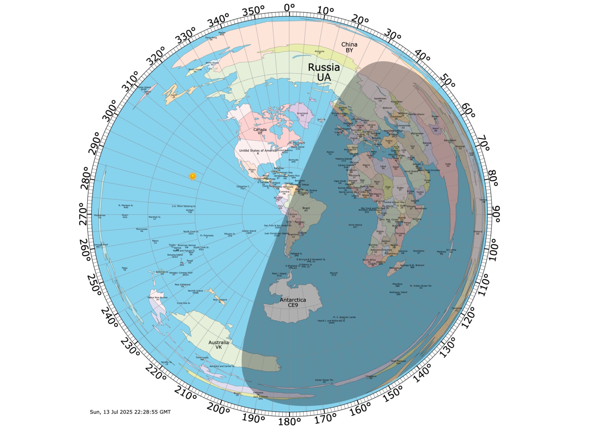 Online coloured Azimuthal Map Generator. By default, this map shows the current gray line. The parts of the Earth that are currently in the sun (i.e., daytime) appear brighter, and the parts of the Earth that are experiencing night appear darker
 -
 How to Design and Build a Field Expedient End-Fed Half-Wave Antenna for 20m, 40m and 80m. This Shorty 80m EFHW comprises a 49:1 autotransformer (to match the very high impedance at the end of a half-wave wire), a half-wavelength wire for 40m (also a quarter-wavelength for 80m), a loading coil and a short tail wire. The coil and the short tail wire (about 6 feet) make up the other quarter wave on 80m.
 -
 This article describes a simple yet effective multi-band vertical HF antenna design that performs exceptionally well across 80m to 10m bands. The antenna consists of a 13.4m wire mounted on a 12.4m Spiderpole, complemented by four 12m radials and a ground rod. Initially tuned with a manual LC circuit, it was later upgraded with a CG3000 remote auto ATU for convenient band switching. Despite antenna modeling software suggesting limited performance on higher frequencies, the system demonstrated excellent DX capabilities across all bands, outperforming more complex vertical antenna designs.
 -
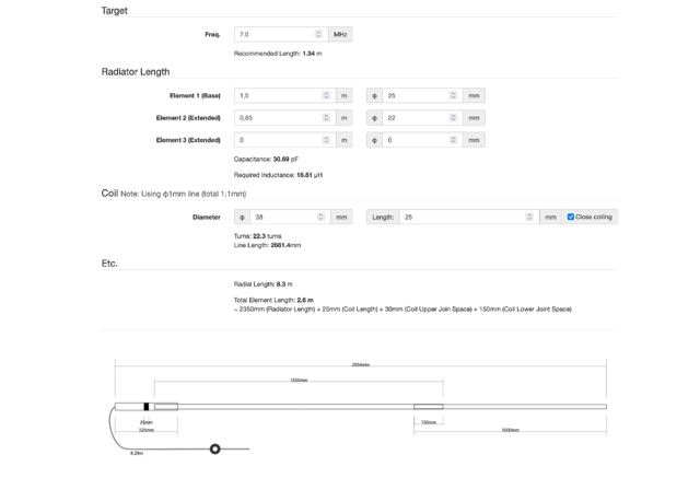
 This article shares the author's experience with building antennas. After putting a large magnetic loop project on hold, they decided to try a base-loaded vertical antenna. The author explains how they chose to design a new antenna from scratch, aiming for a frequency of 7 MHz. They describe the calculations needed to find the right coil inductance and how they used 3D-printed parts for the construction. The article wraps up with results from their initial tests, showing good communication on different bands and highlighting the success of their design.
 -
 The reason for making this antenna was the desire for a vertical (hence DX-ish) antenna that would cover at least 20m that would fit on my 5m fishing pole. This antenna can work on 20m 17m 15m bands and it is suitable for SOTA operations
 -
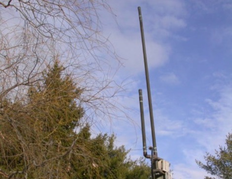
 This is a FULL SIZE quarter-wavelength vertical made on a 18m Spiderbeam fiberglass telescoping Spiderpole
 -
 This article documents the author's journey in building, modifying, and testing a DIY short vertical antenna for 40, 30, and 20 meters, with potential 80m capability. Initially inspired by Parks On The Air (POTA), the author explores pedestrian mobile operation and details various experiments to enhance antenna performance. The piece highlights challenges, SWR tuning, portability, and practical results, emphasizing a balance between efficiency and size. Ultimately, it showcases the adaptability of DIY antennas for portable ham radio applications.
 -
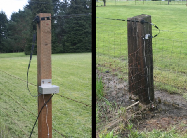 The Beverage we use is a DX Engineering RPS-1 dual directional 360 foot 109,7 m, oriented due North/South, six feet 1,8 m off the ground. The antenna uses 450 ohm ladder line as the antenna, and 75 ohm RG-6u for the feedline. The antenna runs atop the fence between our property and 5 acres of pasture next door.
 -
 Opting for a visually appealing inverted L configuration, G4WIF anchors the End Fed Half Wave antenna to an old clothes line pole, seeking cost-effectiveness in their endeavor. Despite initial misconceptions about transformer components, a £7.95 investment in a T240-43 toroid and DIY mounting container resolves the issue. Reflecting on commercial alternatives, G4WIF's homemade solution proves both economical and sufficient for their amateur radio needs.
 -
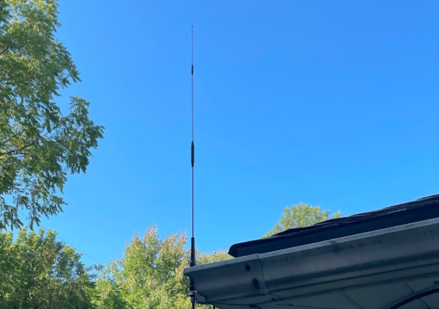 A concept to use common, low-cost parts to mount a VHF/UHF dual-band antenna to help people who have HOA restrictions, are renters, or desire low-visibility characteristics get on the air.
 -
 Originally designed by John Kraus, W8JK in about 1940, this antenna has some interesting properties. The W8JK antenna is 2 (Two) centre-fed double-dipole fed by a pair of anti-phase signals. Small size, simple antenna, offer nice performance but need a tuner. Tested in this project from 30m to 6m bands
 -
 Magnetic loop receive antennas manufacturer. W6LVP loops cover 2200 through 10 meters (135 kHz through 30 MHz) with no tuning or adjustment.
 -
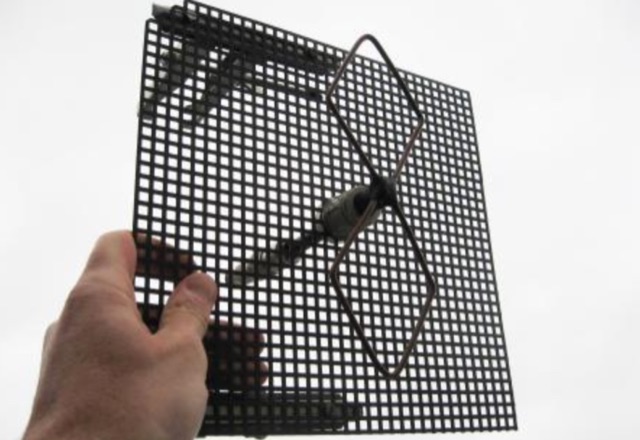 An easy to build double quad antenna that can be used as an antenna for beginners, it features a wide angle providing a generous alignment.
 -
 The author reflects on expanding their antenna for 80m coverage during lockdown. They extend the End Fed Half Wave (EFHW) using a Spiderbeam pole and "cheating" by dog-legging across their garden. Despite challenges, they achieve coverage for multiple bands with minimal cost. Practical Wireless features EFHW antennas, including a pre-made 20m EFHW extended for 40m.
 -
 Schemaric diagram for a 80m, 40m, 30m, 20m EFHW Antenna Antenna Tuner. The tuner has been designed for an antenna length of 41m and the counterpoise 7.5m.
 -
 This page delves into the Inverted V antenna, a source of myths among ham radio operators. The author explores the behavior of this antenna type with a focus on a 20m half-wave dipole positioned 10m above the ground. From Pythagoras to high school math, the article simplifies the calculation of dimensions and angles for setting up an Inverted V antenna. It includes a spreadsheet for calculating hypotenuse length and angles, crucial for antenna setup. Additionally, it provides insight into the radiation pattern of a 'flat' half-wave dipole at 10m height. Useful for hams planning to optimize their antenna setup. In Norwegian.
 -
 Modeling an antenna over real terrain gives you a visual picture of how terrain impacts performance. You can use a model to determine optimum height for antennas on an existing tower, Compare different tower locations for performance, Compare different sites for performance
 -
 The video showcases the setup of a 300 MHz oscillator, a 100W radiofrequency amplifier, and a dipole antenna for transmitting radio waves, leading to the fluorescence of a nearby light bulb. It demonstrates the presence of standing waves on the dipole antenna and how intensity varies along its length. Additionally, the usage of a copper pipe as a receiving antenna is explored, showing changes in intensity depending on alignment and proximity to the transmitter. Finally, a B field antenna sensitive to magnetic fields is introduced, revealing brightness variations in different orientations. The video offers insightful observations on radio wave transmission and reception phenomena.
 -
 This is very common W7IUV Flag Antenna design is based on the PY3AGD antenna because it uses the antenna mounted horizontally and nd it is perfect for my small city lot installation.
 -
 The antenna I built was inspired by a portable delta loop designed by Doug DeMaw, W1FB. Given that I constrained myself to a 50-foot roll of speak wire, I scaled my antenna for the 20M band. Using the formula, 1005 divided by the frequency in megahertz, I calculated a total length of 71 feet (21.6 meters) for the center of the 20M band.
 -
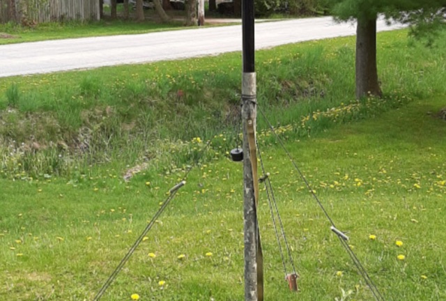 Supporting a telescopic fiberglass antenna pole for ham radio operation. Rather than cumbersome methods like using angle iron or PVC pipes, author employs lightweight tent stakes, toggles, and paracord to secure the pole effectively. With careful knot tying and simple materials, he ensures rapid deployment and stability even in windy conditions, offering a practical solution for outdoor antenna setups.
 -
 144MHz 2m Portable Yagi VHF Beam Antenna. This page contains construction details on a 2 metre 144MHz VHF Yagi beam antenna, designed for portable use.
 -
 The GAWANT Antenna, or Shinagawa Antenna is an half-wave vertical end-fed in a FT817-friendly package
 -
 In this article, Steve G0UIH presents a straightforward guide for constructing a lightweight 15m 3 Element Yagi antenna with impressive performance metrics. With a focus on ease of construction and efficiency, the design boasts a nearly 8.2dbi forward gain and 30db front to back ratio. Utilizing readily available materials and a hairpin match for impedance matching, this Yagi offers broad bandwidth and simple tuning for optimal operation across the 15m band.
 -
 The U01 emergency communications antenna is a versatile, multiband antenna designed for 80/60/40/20/17/15/10m bands, known for its reliability and compact size. It features a broadband transformer wound on various core options like FT82-43, FT114-43, or FT140-43, with the latter capable of handling up to 100W. The antenna incorporates a PCB with options for SMA and BNC connectors, and a weather-proofed design for durability. The lightweight construction, using materials like DX Wire UL and Polyester rope, makes it highly portable. The antenna's design has been tested and proven within the DARC Chapter U01, with multiple build options and detailed documentation available for DIY enthusiasts.
 -
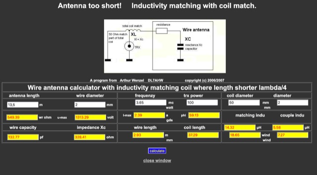 Wire antenna calculator with inductivity matching coil where length shorter lambda/4
 -
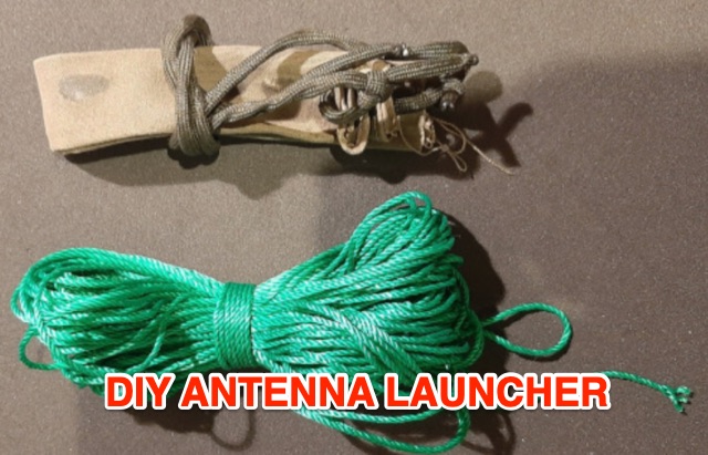 This article explores budget-friendly methods for launching wire antennas into trees, comparing common options like slingshots and professional arborist tools. The author introduces a simple and cost-effective DIY approach using latex balloons, sand, and readily available materials for efficient antenna deployment in the field
 -
 This article discusses suitable first HF antenna options for amateur radio operators with limited space. It recommends an Off-Center Fed (OCF) Dipole and a Vertical Dipole, detailing the installation processes, considerations for stealth and ease of setup, and the characteristics that make them ideal for newcomers. Safety warnings and maintenance tips are provided to ensure effective and secure operation.
 -
 The J-Pole antenna is a common omnidirectional antenna used in amateur radio, particularly on the VHF and UHF bands. This article is an attempt to explore how the J-pole antenna transforms feed-line impedance to free-space impedance, all the while providing gain found only in the more expensive commercial products.
 -
 The original HEXBEAM was developed by Mike Traffic, N1HXA, in the early nineties. It is true that an M over W configured yagi antenna that resembled a butterfly was earlier tried successfully. But the advanced electrical design, the characteristic nesting concept and central terminal post that enable the multi band functionality along with the basic hardware design were all developed by Mike Traffie.
 -
 This antenna is designed for 40, 80 and 160 meters to complement a tri-band beam normally taken on DX peditions for 10, 15 and 20 meters, so six bands can be worked with only two antennas.
 -
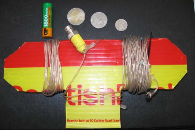
 The author explores a portable version of the half-square antenna, typically a single-band structure. Using a 9:1 unun for versatility, they describe construction with speaker wire, deployment using collapsible poles, and field tests, achieving successful contacts on multiple bands. The article suggests efficient matching methods and concludes with the antenna's integration into the author's portable options.
 -
 This document details the construction of a multi-band end-fed antenna, suitable for situations with limited space for larger antennas. The design utilizes a 1:49 to 1:60 impedance transformer to match a half-wave wire antenna fed at one end. Compared to a traditional dipole, this antenna resembles a highly unbalanced Windom antenna with one very long leg and a virtual short leg. The design eliminates the need for radials but relies on the coax cable shield for grounding. The document recommends using at least 10 meters of coax and installing a common mode filter at the entry point to the shack for improved performance.
 -
 This PDF document reviews the POTA PERformer Antenna by KJ6ER, providing insights and details about its performance and features. The content is aimed at hams looking for information on this specific antenna model to help them make an informed purchasing decision. It contains technical specifications, user experiences, and possibly recommendations for optimal use. The review is valuable for hams interested in portable operation and seeking a reliable antenna solution for Parks on the Air (POTA) activations.
 -
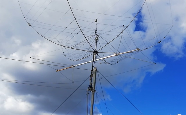
 A comprehensive overview of a 10-band attic antenna system developed for contesting and DXing is presented, covering its evolution and performance. Initially intended in a restricted location, the system has been developed through numerous iterations, using various antenna types such as delta loops and Yagis. Automatic switching, dual-direction capability, and optimum tuning for certain band segments are among the most notable features. The project not only improves operating efficiency but also provides great learning opportunities in antenna design and installation in restricted places.
 -
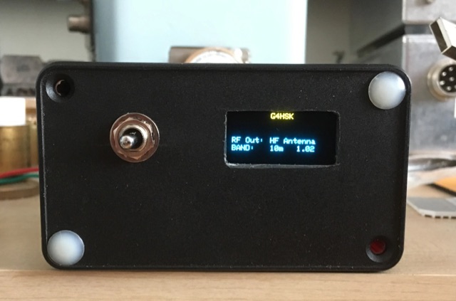 An Arduino Based Antenna Switch For The IC-7300 that monitors the band voltage from the rear accessory socket on the IC-7300. Two RF antenna relays are used to switch to the appropriate output.
 -
 A simple 6dBi Collinear Antenna for LoRa compared to the Lorank8 gateway default antenna.
 -
 This article describes the construction of a three-band vertical antenna for the WARC bands (10, 18, and 24.9 MHz). Unlike a previous design using thin wire requiring a complex matching device, this version uses a telescopic set of pipes, reducing reactances and simplifying the matching device to two coils and two capacitors. The article provides details on the antenna model, the matching device circuit, and tuning methods, including the use of frameless coils and variable capacitors. With proper tuning, the antenna achieves a VSWR not exceeding 1.3 across all bands, demonstrating a practical and efficient design for amateur radio enthusiasts.
 -
 In this article the author describes his personal experience on some antennas for 50 MHz he tested on the field, the six meter Dipole, Vertical, Moxon, a 3 element Yagi and an Omniangle antenna.
 -
 The Bazooka antenna, a coaxial dipole, functions as an omnidirectional antenna with vertical or horizontal polarization. Patented in 1939 and refined in 2006, it features a quarter-wavelength coaxial cable with separated conductors. The outer conductor connects to a sleeve, while the inner conductor extends vertically. Initially complex, it has been simplified for versatile use, including military applications. Adding elements can modify its behavior for NVIS or Yagi-Uda configurations. Experiments in 2007 at the Campus de Pesquisas GeofÃsicas in Paula Freitas-PR demonstrated consistent VHF and UHF performance, showing reliable return loss measurements despite variable weather.
 -
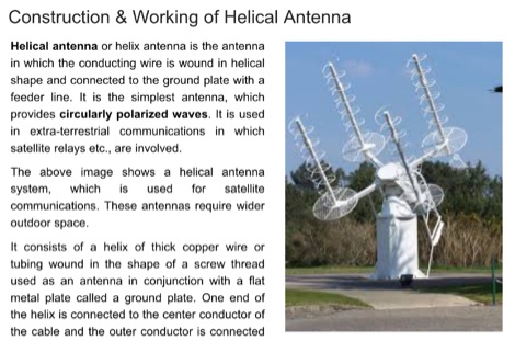 Helical antenna or helix antenna is the antenna in which the conducting wire is wound in helical shape and connected to the ground plate with a feeder line. It is the simplest antenna, which provides circularly polarized waves.
 -
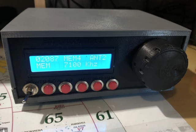 This project is for those ham amateurs who do not have a commercial one . It's easy to build with a soldering iron, a plastic case and a little knowledge of arduino. The controller is made with budget components you can find easily in Internet. The main component is a cnc shield that fits over an Arduino Uno. Both made a compact, small and cheap controller.
 -
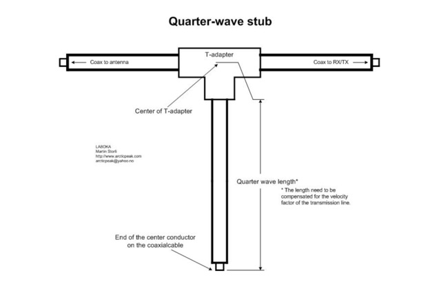 The Quarter-wave stub can be used for many purposes. If it is left with an open end it can be used as a notch filter to attenuate certain frequencies. A quarter wave length of a transmission line can also be used as an impedance transformer, to know more about the Quarter-wave impedance transformer