Search results
Query: RF
Links: 639 | Categories: 67
This query is too generic. Please try adding an additional term to focus your research.
Categories
- Manufacturers > Interfaces
- Technical Reference > Radio Frequency Interference
- Technical Reference > Amplifiers > RF Amplifiers Theory
- Technical Reference > RF Design
- Software > RF Design
- Technical Reference > Test Equipment > RF Probe
- Technical Reference > RF Safety
- Technical Reference > RF Signal Generators
- Technical Reference > Test Equipment > RF Sweep Generator
- Shopping and Services > RF Tubes
- Software > RF Coverage Mapping
- Technical Reference > Sound Card Radio Interfacing
- Shopping and Services > Accessories
- Radio Equipment > HF Amplifiers > Ameritron AL-80B
- Manufacturers > Amplifiers
- Technical Reference > Amplifiers
- Technical Reference > APRS
- Technical Reference > Attenuators
- Antennas > Baluns
- Radio Equipment > HF Portable Antenna > Buddipole
- Manufacturers > Cable and Connectors
- Shopping and Services > Cables and Connectors
- Technical Reference > Calculators
- Antennas > Feed Lines > Choke
- Antennas > Feed Lines > Coax Stubs
- Radio Equipment > HF Vertical Antenna > Cushcraft R5
- Manufacturers > Digital and Packet Radio
- Ham Radio > Clubs > Europe > UK > Eastern England
- Antennas > EH
- Radio Equipment > HF Transceivers > Elecraft K4
-
 This article discusses the potential for solar power systems to coexist harmoniously with amateur radio, challenging the notion that they are inherently incompatible. Drawing from personal experience, the author emphasizes the importance of selecting RF-quiet components, focusing on series-string Sunny Boy grid-tie inverters. The article also highlights considerations for system design and limitations based on roof orientation, shading, and array size. Overall, it presents a valuable perspective on creating a radio-friendly solar PV setup.
 -
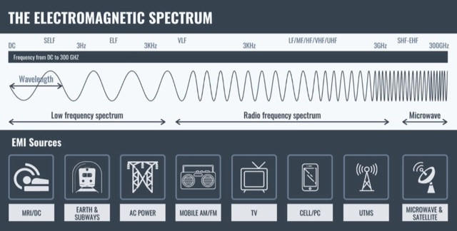 Radio Frequency Interference (RFI) has always been a source of concern for the Radio Amateur. Until the recent introduction of complex circuitry in the home, our communications gear has been the main source of potential RFI. In this computerized age of ours, increasingly complex and sensitive receivers are being barraged by these and other sources of RFI.
 -
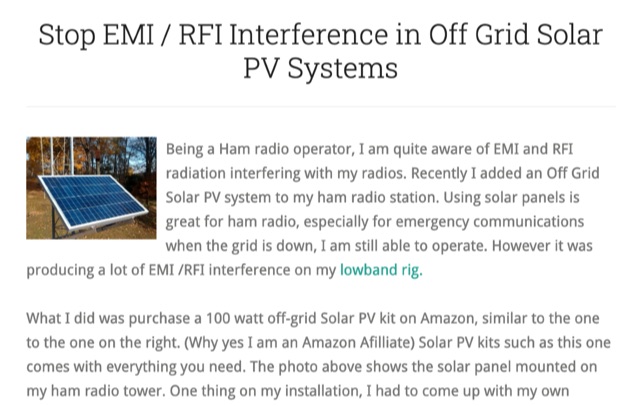 Stop EMI RFI Interference in Off Grid Solar PV Systems, in this article the author provides hints on tracking down the EMI or RFI source, shielding and grounding in order to eliminate interferences on the whole HF and VHF ham radio bands
 -
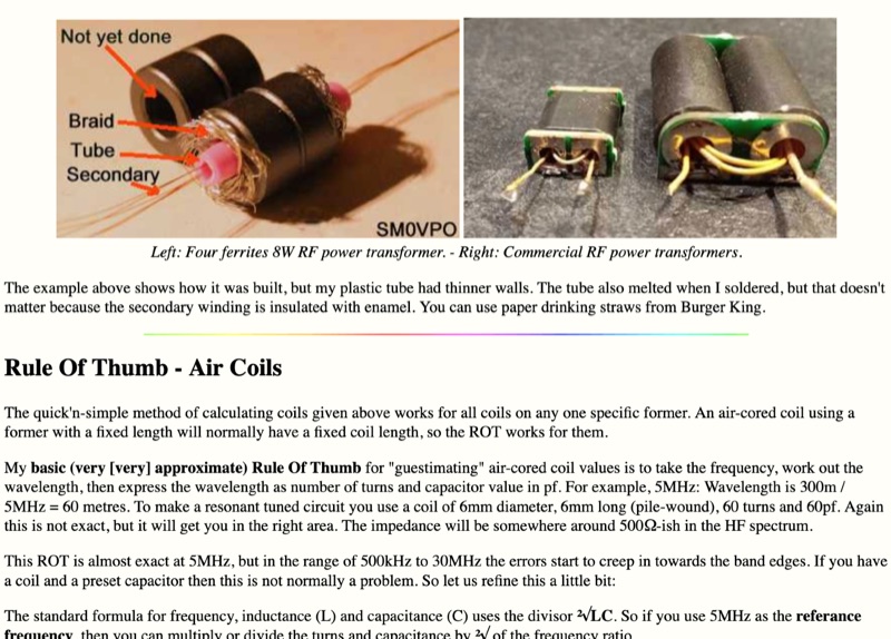 Demonstrates practical **rules of thumb** for selecting and utilizing ferrites and coils in amateur radio projects, particularly for RF applications up to 30 MHz. It addresses common challenges like determining appropriate ferrite grades and estimating L/C values without precise specifications. The resource details the author's experience with readily available grey ferrites, noting their suitability for HF work, and provides guidance on constructing **baluns** and RF chokes, balancing inductance for lower frequencies against inter-wire capacitance for higher frequencies. It also outlines a method for estimating power handling based on ferrite weight, suggesting a 1-gram ferrite can manage over 2 Watts, and offers a technique for evaluating unknown ferrites by winding 10 turns and measuring resonance with a 1 nF capacitor. This approach emphasizes a hands-on, iterative method for balun winding and adjustment, allowing operators to quickly approximate component values. The article compares the characteristics of ferrite-cored coils with air-cored coils, highlighting the reduced pickup and radiation of ferrite designs. It refines the air-coil estimation method for frequencies between 2.5 MHz and 10 MHz and provides a scaling factor for frequencies outside this range, aiming to get operators into the correct general area for their designs. The author's standardized ferrite choice (RND Components 165-00182) is presented as a practical example for reproducible projects.
 -
 Illustrates the construction of a mini ununtenna, focusing on practical design elements and component specifications for amateur radio operators. The guide covers the winding of the unun transformer, selection of appropriate ferrite core material, and integration of the radiating element. It specifies wire gauges, core dimensions, and connection points, providing a clear pathway for replication by hams. Compares the ununtenna's performance characteristics against other common wire antennas, highlighting its compact footprint and broadband capabilities. It discusses impedance matching considerations and offers insights into optimizing the antenna for various HF bands, making it suitable for portable operations or limited space installations.
 -
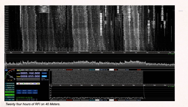 Demonstrates the application of Software-Defined Radios (SDRs) as effective tools for conducting Radio Frequency Interference (RFI) site surveys. The resource details the methodology for capturing and analyzing RFI, specifically focusing on the 80-meter band over a 24-hour period. It outlines the setup of an SDR-based survey tool, utilizing software like _S-Meter Lite_ and _Spectrum Lab_ to visualize and quantify noise sources. The article emphasizes the SDR's wideband capabilities, which allow for comprehensive identification and documentation of RFI across broad frequency ranges, crucial for effective mitigation strategies. The analysis presents practical results, illustrating how continuous monitoring can reveal intermittent RFI sources that might otherwise go undetected. For instance, the survey identified noise peaks exceeding **S9+20dB** on 80 meters during specific hours, correlating with local appliance usage. The methodology provides a repeatable process for hams to characterize their local noise floor, enabling targeted RFI suppression efforts and improving weak-signal reception, particularly for DXing and contesting.
 -
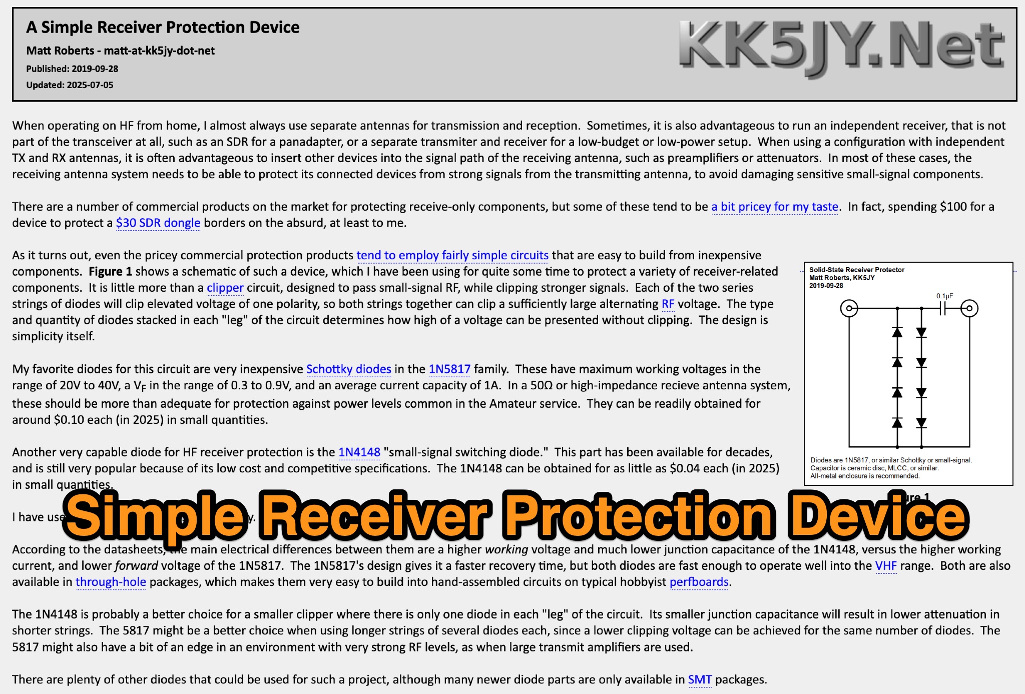 This page discusses a simple receiver protection device designed by Matt Roberts for hams. The article details the purpose, construction, and usage of the RF clipper, providing useful information for ham radio operators looking to protect their equipment from RF overload. The content is practical and informative, offering a solution to a common issue faced by hams.
 -
 open890 is a web-based UI for the Kenwood TS-890S amateur radio, and features good usability, clean design, and high-speed bandscope/audio scope displays, among other features not available either on the radio itself, or in the ARCP remote control software. It is currently only designed to interface with the TS-890 via a LAN (or wifi) connection, and not a USB/serial connection. It may work with the TS-990, as the command set is very similar, but is currently untested.
 -
 This page provides information on how to design an Off-Center-Fed Dipole (OCFD) antenna, suitable for amateur HF bands like 80 meters or 40 meters. The antenna design allows for VSWR minima on multiple bands, making it a good choice for multi-band use. Learn how to create an OCFD antenna in either flat-top or inverted-Vee form using a single support. The page also offers tools to generate radiation patterns, VSWR charts, and antenna current diagrams for your specific antenna design, helping hams understand performance factors. Ideal for ham radio operators looking to build their own effective antennas.
 -
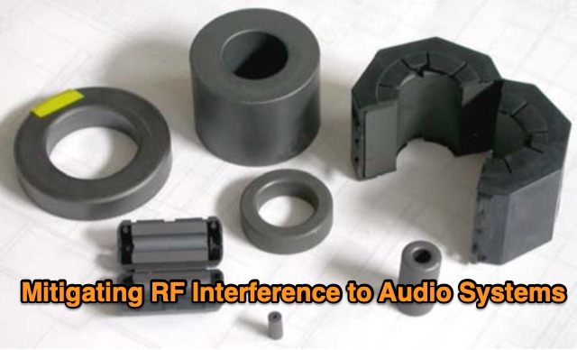 In this study, the author builds upon Muncy's research, demonstrating that radio-frequency current on cable shields affects audio systems through the "pin 1 problem" and shield-current-induced noise (SCIN). An enhanced equivalent circuit for ferrite chokes is proposed, addressing dimensional resonance and inductor self-resonance. Field tests confirm that chokes reduce interference across 500 kHz to 1,000 MHz. Guidelines for diagnosing and mitigating EMI from various sources are provided for product development and field installations.
 -
 The Big Gun's Guide" is a comprehensive exploration of low-band propagation, aimed at serious Amateur Radio operators. It delves into the complex physics of the ionosphere at lower frequencies, contrasting it with HF propagation. The book covers essential topics like ionospheric fundamentals, propagation mechanisms, magneto-ionic effects, and disturbances. It also addresses the challenges of low-band DXing and provides insights for overcoming them. Brown's work is detailed and technical, offering valuable knowledge for those seeking to master the intricacies of low-band communication
 -
 Chris VK3QB, Luke VK3HJ and Alan VK6CQ will be active from Norfolk Island - IOTA OC-005 14 April - 25 April 2022 (UTC)
 -
 Effective suppression of harmonics and parasitic radiation from HF transmitters is crucial, especially with the increasing sensitivity of VHF/UHF radio channels to interference. This project details a hybrid low-pass filter (LPF) designed to operate across the HF bands up to 51 MHz, making it suitable for 6-meter band operations while providing deep VHF/UHF suppression. The design addresses the challenge of modern interference landscapes, where even microvolt-level signals can disrupt wireless sensors and other simple VHF/UHF receivers. The filter utilizes a single elliptic link, combining high cutoff steepness with robust suppression in the hundreds of megahertz range. A key feature is the use of only two standard capacitor values, simplifying construction and component sourcing. The article provides a detailed schematic, performance characteristics, and _RFSim99_ model file, demonstrating a reflection coefficient S11 below 0.017 (VSWR < 1.03) across 1-51 MHz, ensuring minimal degradation to the antenna system. Construction notes include coil winding specifications and capacitor selection guidance, with recommendations for _FR-4_ assembly. Two capacitor sets are presented, with the first variant recommended for its lower RF current demands, keeping currents below 3 A at 1 kW passing power at 51 MHz. Fine-tuning involves adjusting frameless coils, with considerations for capacitor tolerance and high-frequency capacitance measurement accuracy.
 -
 This program simplifies the complex jumper calculations for the PRF1520 radio, which can be a pain to determine manually. It supports common crystal frequencies and channel spacings, advising if a desired frequency is achievable. A recent feature allows determining unknown frequencies of a newly obtained radio by setting the jumper positions and other parameters.
 -
 This article demonstrates how to convert an existing tower into a dual-band vertical antenna for 80- and 160-meter DX operation. Using EZNEC modeling and practical design principles, the authors achieved a low-profile, efficient setup with a single coax feed line, no moving parts, and optimal radiation patterns. The system integrates an 80-meter vertical wire and a 160-meter shunt-fed gamma match for simultaneous operation. Detailed construction insights, including feed system and capacitor configurations, offer a reliable, full-legal-power solution.
 -
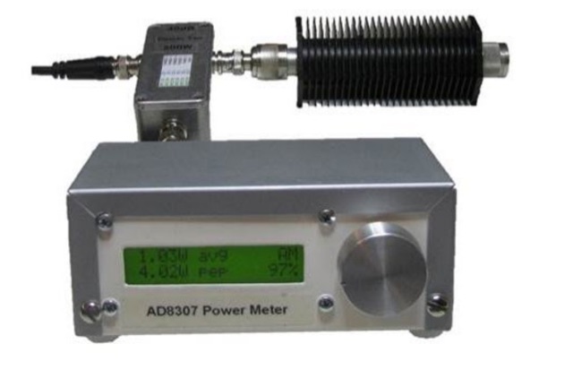 This project goal is to construct a versatile and informative RF power meter. The user-friendly interface, comprehensive power measurement capabilities, and AM detection function make it a valuable tool for various RF applications
 -
 Designing a collapsible 6-meter beam antenna involves careful consideration of element geometry and feedline matching, as demonstrated by VE3SMA's project. The construction draws inspiration from foldable dipole concepts and established wire beam designs like the Penn. State 40m beam and the DJ4SA Spiderbeam. Utilizing **4NEC2 modeling**, the author optimized element lengths for gain and bandwidth, observing the impact of end loops on resonant frequency and the need for compensation. Feeding the approximately 25-ohm balanced antenna with 50-ohm unbalanced cable required a specialized network. This setup incorporates a choke **balun** and a matching section built from two series quarter-wave transformers using readily available 75-ohm cable. On-the-air results validate the design, including a successful 1st double hop Es QSO with 10 Watts and satisfactory performance in the CW WW VHF Contest from FN05, where 41 grids were worked with 100 Watts, showing improved performance over a simple dipole.
 -
 Outlines the essential steps for successfully activating a **Summits on the Air (SOTA)** peak, providing a structured approach for amateur radio operators participating in this popular award program. It details crucial pre-activation planning, including navigating the SOTA website, setting up a SOTA Data account, and consulting the **Association Reference Manual (ARM)** for specific regional rules and peak information. The guide also covers using mapping resources like adventureradio.de and lists ofjohn.com to identify suitable summits and check access conditions. The document emphasizes safety during the activation, advising operators to monitor weather, carry rain gear, and plan ample time for the ascent and descent. It specifies the **4-QSO minimum** requirement within the Activation Zone and recommends calling "CQ SOTA" on traditional QRP or VHF calling frequencies. The guide also suggests using local 2m FM repeaters for safety communications and spotting, while clarifying that repeater QSOs do not count for SOTA points. Post-activation activities include submitting logs to sotadata.org.uk, uploading trip reports to share experiences with future activators, and promoting SOTA participation on various reflectors. The guide highlights the program's appeal through its awards system for both activators and chasers, encouraging new participants in North America.
 -
 When installing a mobile antenna, optimal placement significantly impacts performance. Factors such as gain, antenna type, ground plane availability, mounting style, and environment must be considered. Antenna designs, such as 1/4 wave and 5/8 wave, have distinct radiation patterns ideal for specific settings—urban areas or flat terrains, respectively. Ground plane size requirements differ by frequency, impacting effectiveness. Among vehicle mounting options, the car roof center provides the best ground plane and minimal obstruction, ensuring peak performance, especially at higher frequencies like 800 MHz.
 -
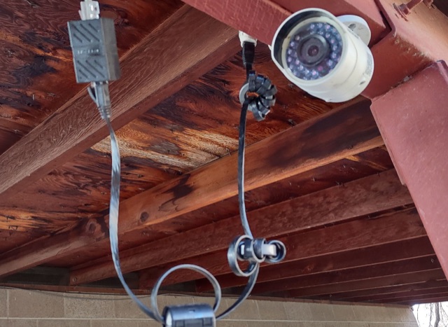 Hams can be annoyed by noise from PoE cameras and access points. These devices and their long cables act like antennas, picking up and spreading unwanted radio signals. By wrapping ferrites around the cable will reduce this noise. It won't silence it completely, but it can make a big difference.
 -
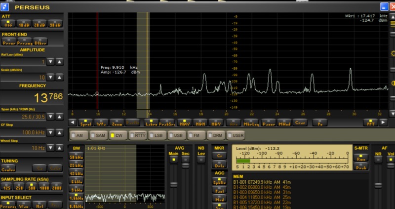 Investigates the performance characteristics of the _AAA-1_ active loop antenna across Very Low Frequency (VLF) and Low Frequency (LF) bands. It details the antenna's frequency response, explaining how a small loop with a low input resistance trans-impedance amplifier maintains a flat frequency response to electromagnetic field intensity E. The document illustrates current source and Thevenen equivalent circuit models for small loops, emphasizing the transition between these models based on frequency and load impedance. Measurement setups for both high frequency and VLF/LF responses are presented with diagrams, including methods for simulating current and voltage sources. The analysis includes normalized plots of the _AAA-1_'s frequency response for three distinct loop inductances, derived from measurements using a _Perseus SDR_ at 1 kHz bandwidth. It provides calculations for the noise floor at VLF/LF frequencies, comparing ambient noise levels with the antenna's internal noise floor. The resource also documents practical reception experiments in a semi-urban environment, showcasing successful reception of time transmitters like _MSF_ at 60 KHz and _SAQ_ at 17.2 KHz, along with various navy digital transmissions and Russian Alfa beacons.
 -
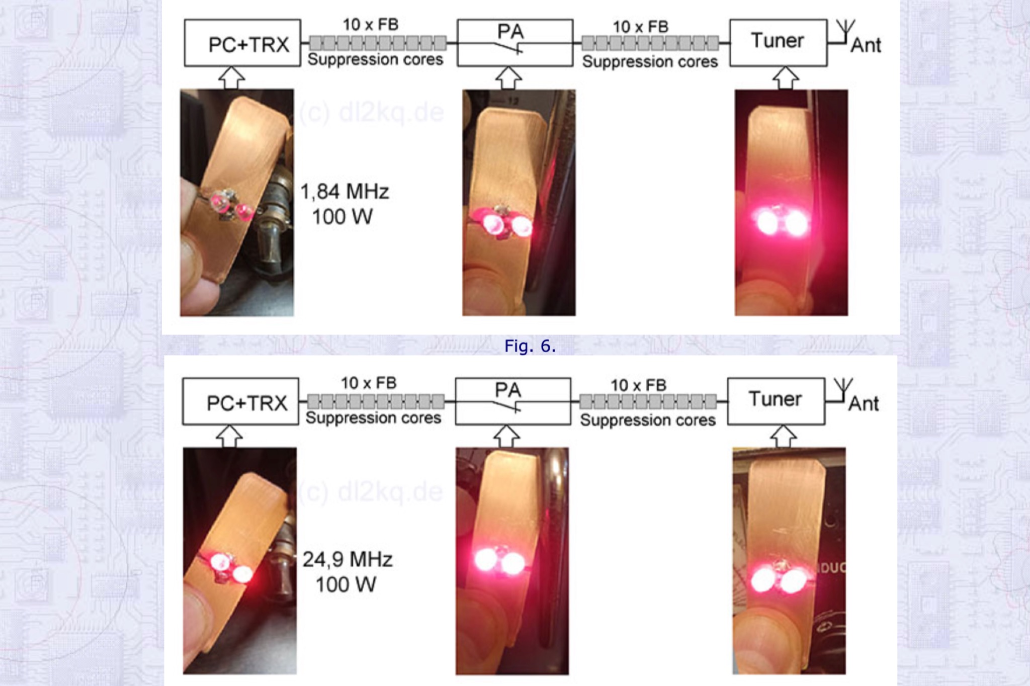 Detecting stray RF voltages on station grounds, chassis, and interconnecting cables is crucial for preventing program and hardware failures in the shack. This article details the construction and application of an LED RF V-probe, which offers significantly higher sensitivity compared to conventional neon lamp indicators. The probe leverages two specific properties of modern red LEDs: their ability to glow at microampere currents and their rectification capability at frequencies up to tens of megahertz. The design features a simple circuit with two LEDs, allowing for indication of both positive and negative RF voltage half-waves. The minimum detectable RF voltage is approximately 2 V, a substantial improvement over the 40-60 V threshold of neon bulbs. The resource illustrates the probe's physical construction on a PCB and provides a direct comparison demonstrating its superior sensitivity in detecting RF fields near a coil. Two operational modes are described: a non-contact mode for high RF voltages (above 15-20 V) and a direct-contact mode for measuring lower RF voltages, with a safety caution for the latter. Practical examples show the probe's use in analyzing RF voltage distribution across a radio station setup at 1.84 MHz and 24.9 MHz, revealing insights into common-mode current issues and the effectiveness of mitigation strategies like adding radials.
 -
 This excel workbook addresses the issue of power loss in transmission lines with complex characteristic impedance ZoZo​. It illustrates the discrepancy between actual loss (0.35 dB) and matched line loss (0.6 dB) using a simplified example, highlighting potential software tool limitations. The RF Feedline Power-Loss Calculator provides accurate end-to-end loss assessments for both microwave and RF applications. This tool is suitable for engineers and students and is compatible with Windows versions of Excel 2016 or later, though it is not compatible with Macintosh systems.
 -
 Demonstrates optimizing an **ON4UN-type 4 Square antenna** for enhanced performance across the lower HF bands, specifically 160m through 10m. The article details a design that utilizes a single support structure for the vertical elements, significantly reducing construction complexity and cost compared to traditional multi-tower setups. It emphasizes the use of **elevated radials** to achieve improved gain and a lower receive noise floor, providing insights into the design principles and practical installation tips for this directional array. K0UO shares his experience with this low-cost, high-gain solution, including the integration of a hybrid coupler phaser. The author's field testing confirms the benefits of elevated radials in achieving better far-field performance. The optimized 4 Square design offers a practical alternative for hams seeking a directional array without the extensive infrastructure typically required. Comparisons are drawn to traditional ground-mounted radial systems, highlighting the superior gain and reduced noise characteristics observed with the elevated configuration, making it a compelling option for DXing and contesting on the lower HF frequencies.
 -
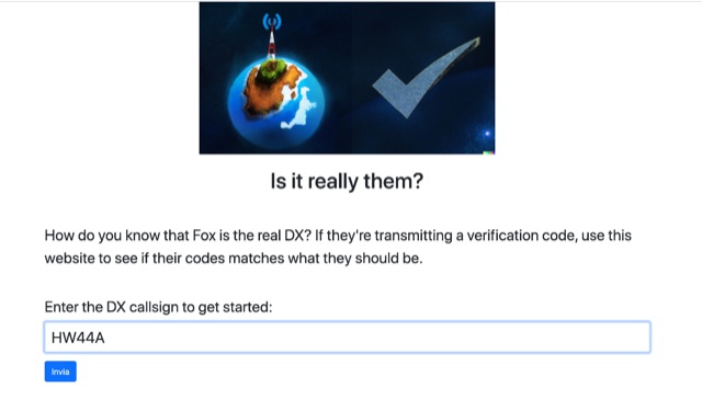 How do you know that Fox is the real DX? If they are transmitting a verification code, use this website to see if their codes matches what they should be. Enter the DX callsign and you will get last five minutes of verification codes for the dx station callsing.
 -
 This comprehensive article dispels common misconceptions about Standing Wave Ratio (SWR) in amateur radio. The author explains that SWR is not an antenna property but a measure of the entire antenna system, representing the mismatch between transmission line and load impedance. Contrary to popular belief, modest SWR values (under 3:1) typically cause minimal power loss in HF applications. The article demonstrates mathematically why obsession with achieving 1:1 SWR is often unnecessary, explains when SWR matters more (QRO, QRP, VHF/UHF), and explores effective matching techniques including proper ATU placement and quarter-wavelength transformers.
 -
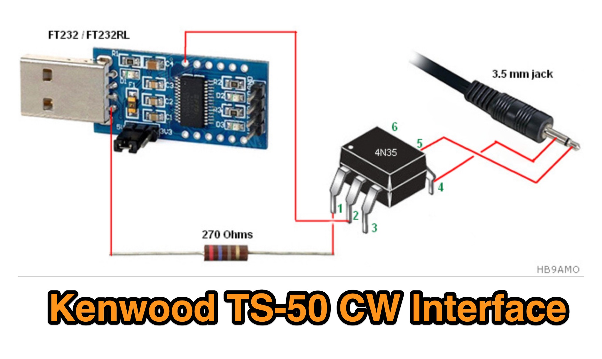 The Kenwood TS-50 is a reliable 25-year-old mobile HF radio, widely used in DX operations but lacking CAT and DATA ports for modern logging or contest software. To overcome this, a custom CW interface was built using an USB to TTL module (FT232/FT232RL) and an optocoupler (e.g., 4N25, H11A1) for galvanic isolation. This setup enables the TS-50 to connect with a computer via USB, facilitating integration with software like LOGGER32 and Win-Test. The interface is cost-effective and driver-free for Windows XP and 7, making it an accessible solution for enhancing the TS-50's functionality.
 -
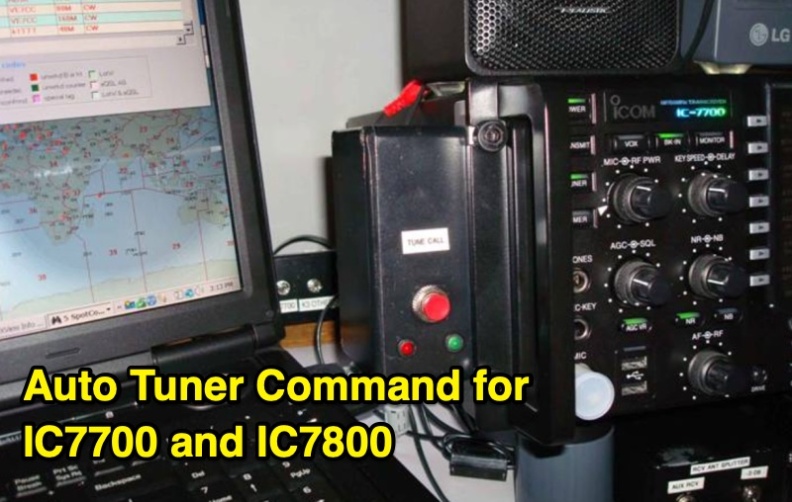 An Arduino-based interface provides a remote tuner call command for Icom **IC7700** and **IC7800** transceivers, addressing the lack of a built-in function for external tuners such as the MFJ 998RT. This setup initiates a low-power transmit signal, typically 15 watts, allowing the remote autotuner to perform its matching sequence. The article details the required CI-V line communication and modifications to existing Arduino code, specifically referencing contributions from Jean-Jacques ON7EQ for improved Icom interrogation routines. The system involves a sequence of steps: storing the transceiver's current mode and power, disabling the internal autotuner, activating a control relay to interrupt the amplifier line, switching to RTTY mode at low power, and initiating transmit. The transmit duration is manually controlled by the operator, observing the SWR meter until a low SWR is achieved, then a second button press stops the transmission. A built-in 4-second transmit limit provides a safety measure. After tuning, the routine restores the original mode and power settings, re-enables the internal autotuner, and performs a brief 2-second RTTY transmission for internal tuner adjustment. The circuit diagram includes a Panasonic form 2 relay for amp control and emphasizes critical delays in the Arduino code for stable operation at 9600 baud CI-V communication. Compatibility with logging software like DXLab, N1MM, and N3FJP is noted, with specific interrogation time settings required to avoid conflicts.
 -
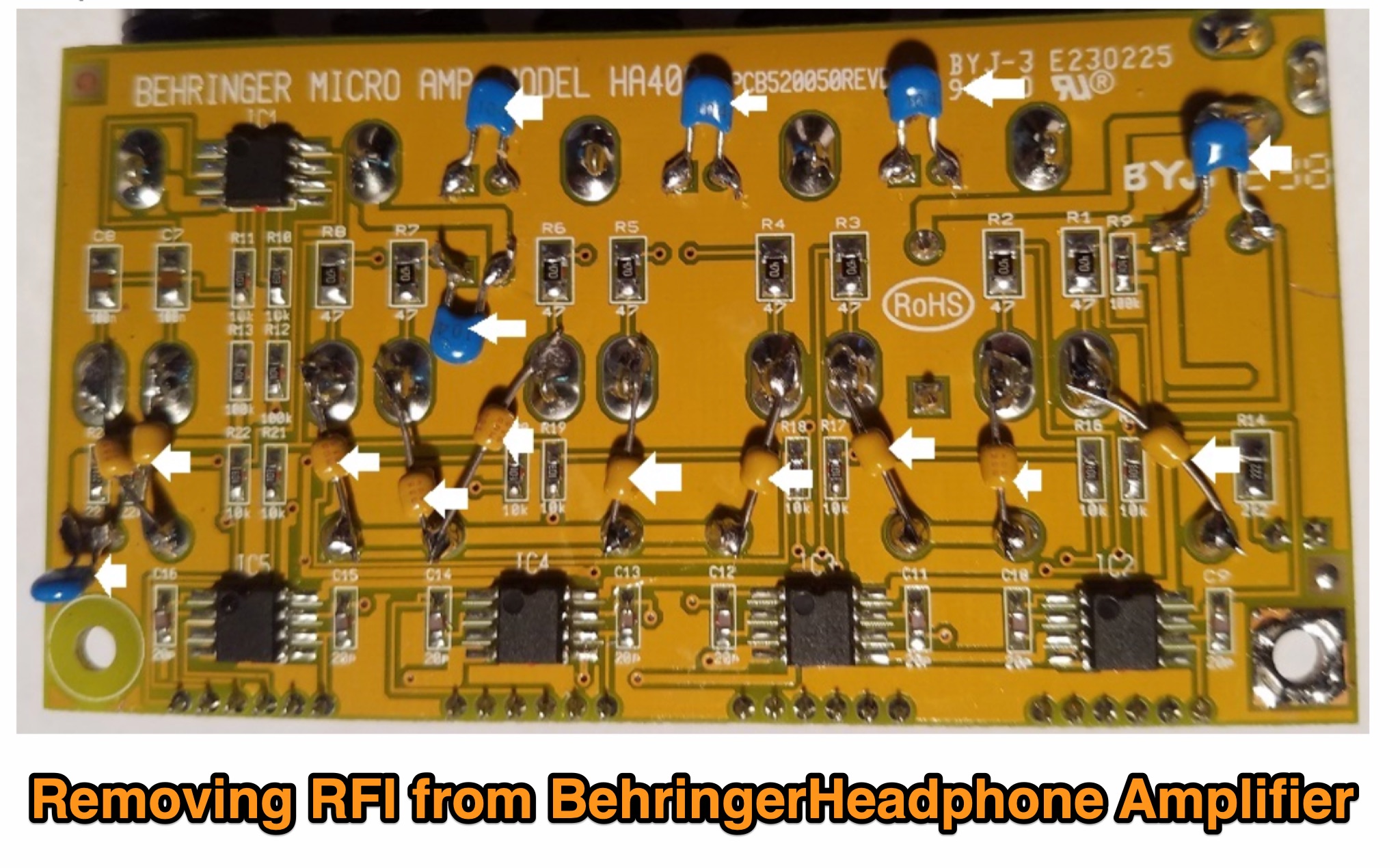 Learn how to eliminate RF interference from your Behringer HA400 headphone amplifier for a better listening experience. Discover the simple modifications needed to prevent distortion caused by RF in your audio setup. Follow the step-by-step instructions provided by WB5NHL Ham Radio to improve the performance of your headphone amplifier in ham radio activities.
 -
 Manufacturer of SDR Motherboards LA9310, Si5510, i.MX8MP, 4GB LPDDR4. The RFNM motherboard is a new concept, so it's worth taking a few seconds to understand it. In a nutshell, the most complicated parts are consolidated into a single block, the motherboard, and all of the interesting and fun bits are exposed via the RFNM Interface to daughterboards.
 -
 Understanding how radio frequency interference (RFI) is coupled into equipment and subsequently detected is crucial for amateur radio operators. This guide delves into the fundamental mechanisms of RFI, particularly focusing on detection at semiconductor junctions and the unintended antenna action of system wiring. It explains that most RFI detection follows a square law, meaning a 6 dB reduction in RF signal can result in a 12 dB drop in detected audio, offering a practical approach to mitigation. The resource also clarifies the concept of common mode versus differential mode signals, detailing how cable imperfections can convert common mode antenna current into differential signals. It addresses the critical "Pin 1 Problem" in audio interfacing, a common design flaw where cable shields connect to the circuit board instead of the shielding enclosure, leading to significant RFI issues. Practical solutions, such as proper shielding, using twisted-pair cables, and strategic bonding of equipment, are discussed to effectively reduce or eliminate RFI. The guide emphasizes the importance of proper filtering and the often-misunderstood concept of "ground" in electrical systems, distinguishing between earth ground, equipment ground, and circuit common. It provides insights into minimizing loop area in wiring to reduce inductively coupled noise and antenna action, drawing on the author's extensive engineering background and ham radio experience.
 -
 The Yaesu VX-6R USB Programming Interface is a reliable solution for programming the Yaesu VX-6R handheld radio using USB. Based on the FT232RL chip, it replaces older RS232 interfaces and USB converters, ensuring stable communication. The design integrates a buffering circuit with a Sparkfun breakout board, featuring TX and RX LEDs for easy monitoring. The compact interface connects to the radio via a four-pin header, with a solder bridge option for radios requiring separate data lines. This setup has proven reliable and versatile, allowing the FT232RL to be repurposed for other projects.
 -
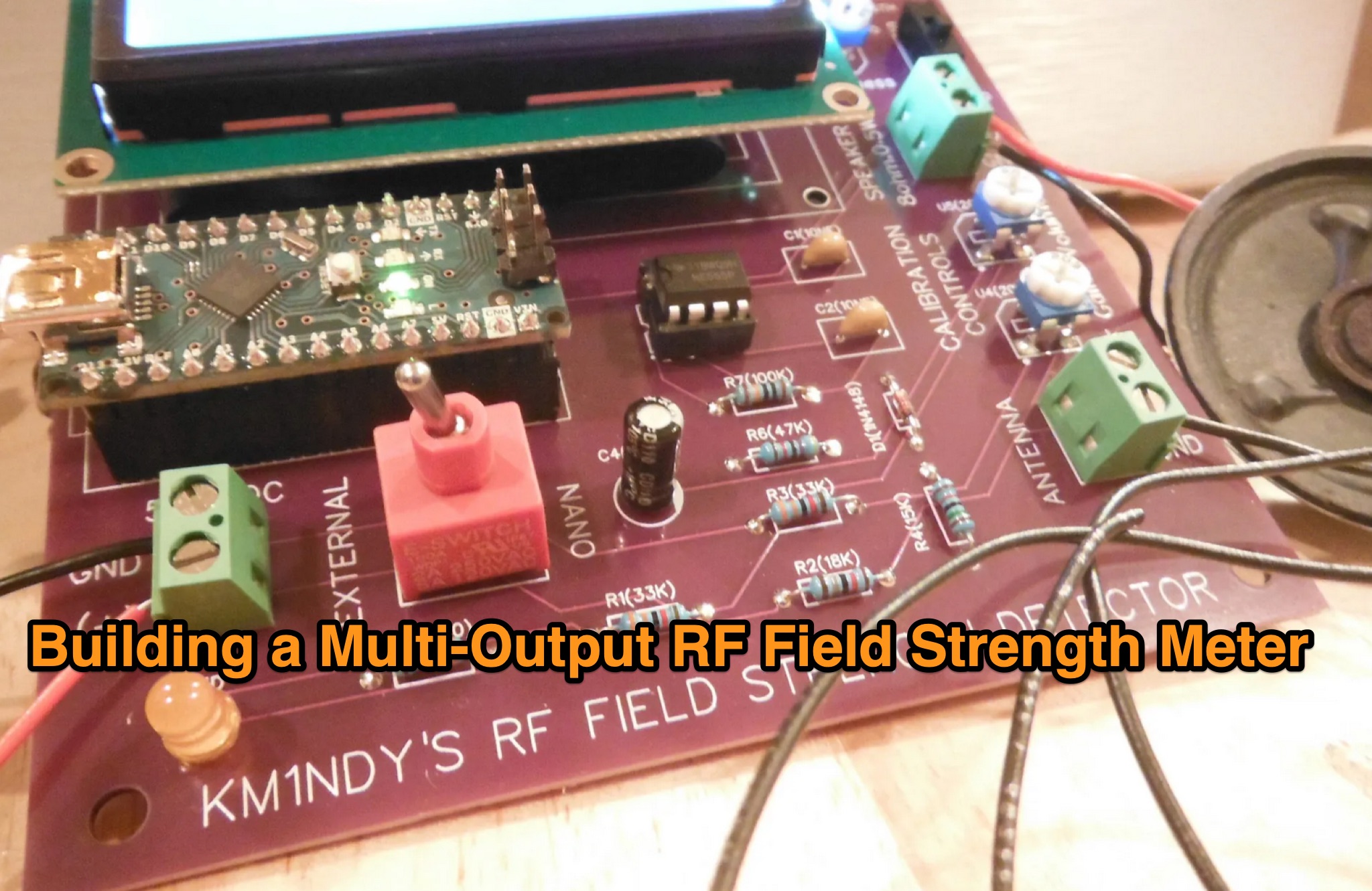 This article describes a DIY RF field strength meter project inspired by VK3YE's "The Squeakie" design. The device, built around a 555 timer IC and a 1N4148 diode, converts RF signal strength into audible tones with proportional pitch. The author enhanced the original design by adding volume control, LED indication, and digital readout capabilities using an Arduino Nano and LCD display. The completed project functions as a versatile RF detection tool, suitable for antenna testing and fox hunting, while offering multiple output methods: audio, visual, and digital measurement display.
 -
 The article details how to eliminate Radio Frequency Interference (RFI) from the Behringer HA400 headphone amplifier when used in ham radio setups. While the HA400 is praised for its quality and affordability, it was not designed for RF environments, causing distortion when used with a 500-watt radio station. Initial attempts using clamp-on ferrites on the headphone and power cables only partially resolved the issue. Upon opening the unit, the author discovered the circuit lacked RF bypassing components. The solution involved installing 0.1μF (104) capacitors at key points in the circuit: the power supply input, audio circuits, and op amp inputs. This modification, combined with the external ferrites, completely eliminated the RFI problem, making the unit suitable for ham radio operations.
 -
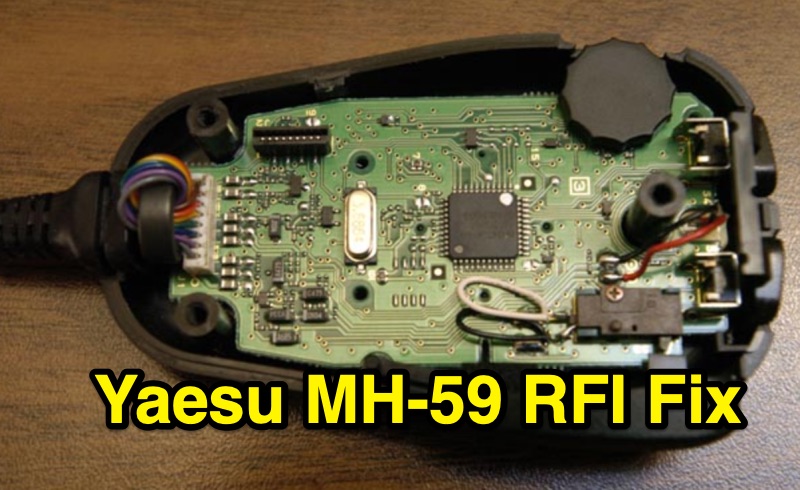 This resource details a practical RFI fix for the Yaesu MH-59 microphone, specifically addressing interference encountered during Field Day 2004 operations. The modification involves installing a small toroid core onto the microphone's internal cable connector. The author, AE7Q, describes the process: purchasing a ½" outer diameter, ¼" inner diameter toroid core from a surplus store, opening the MH-59, unplugging the cable connector from the circuit board, looping the cable through the toroid, and then reassembling the microphone. This fix is intended for amateur radio operators experiencing RFI with their Yaesu MH-59 microphone, particularly in environments with strong RF fields like those found at Field Day events. The page also directs users to the AE7Q message board for questions and comments.
 -
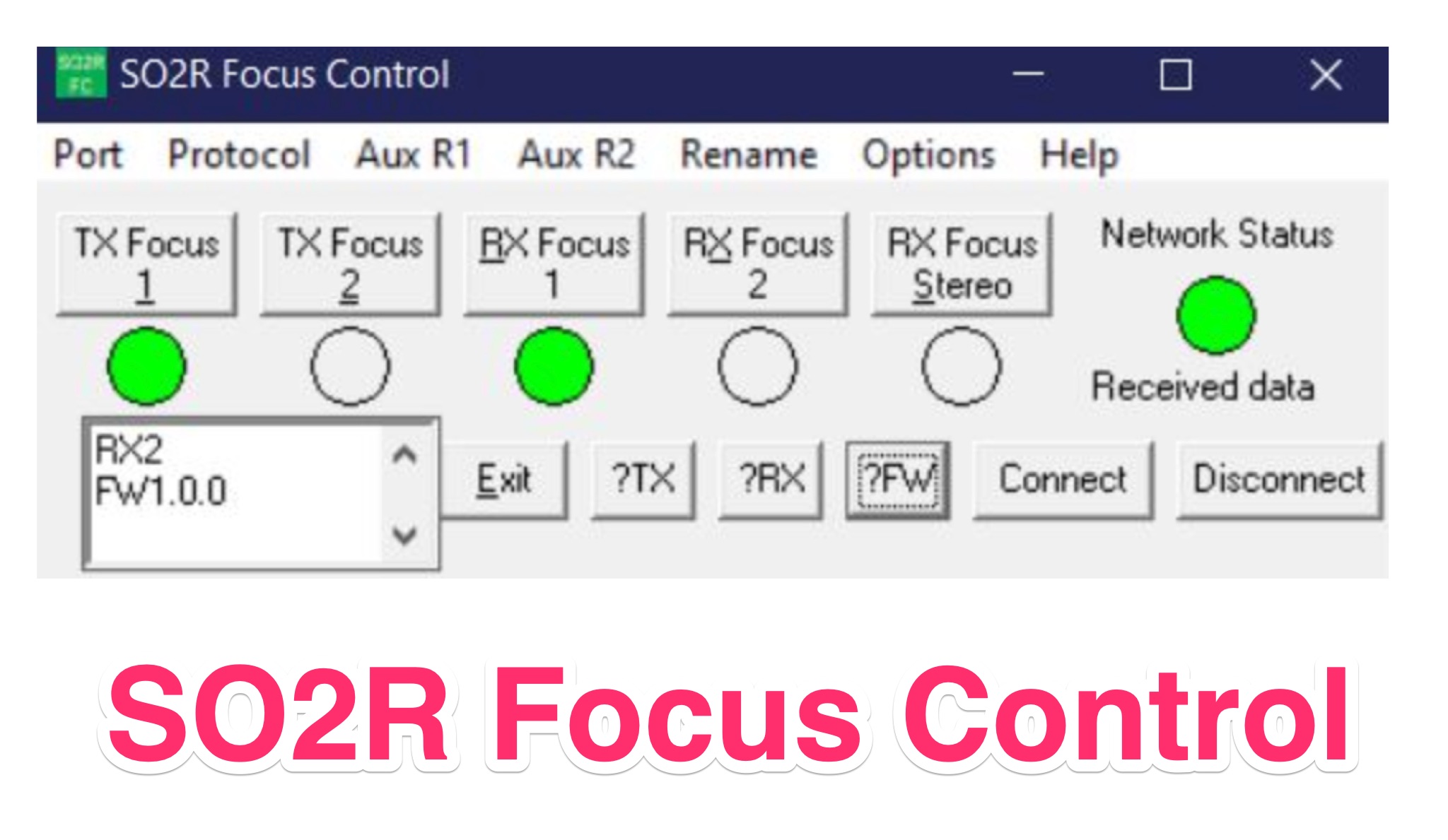 SO2R Focus Control and SO2R FC Server are freeware VB6-based tools enabling remote or local control of modern SO2R controllers (supporting OTRSP and MK2R protocols) outside contest logging sessions. The client (SO2R Focus Control) manages serial-connected controllers and can interface remotely via LAN or internet using the optional SO2R FC Server, which supports up to two concurrent clients. Key features include AUX port control with customizable labels, interlock options, AES-256 encrypted network communication, and compatibility from Windows XP through Windows 11. Designed for operators needing flexible station control—especially for remote antenna switching—both programs install cleanly via NSIS and uninstall completely.
 -
 Demonstrates a LoRa APRS Tracker project featuring a comprehensive menu system for message management, weather requests, and monitoring nearby trackers. The device supports adjustable display eco mode and screen brightness, optimizing power consumption by dynamically changing processor speed from 240MHz to 80MHz. GPS beacons are encoded for efficient RF transmission, and an OLED screen displays altitude, speed, course, _BME280_ weather data, or new message counts, along with recently heard stations. Bluetooth connectivity enables operation as a TNC with Android (APRSdroid) or iPhone (APRS.fi app), providing LED and sound notifications for transmissions and received messages. The integrated BME280 module facilitates weather data display and transmission, with Winlink mail support via _APRSLink_. The tracker can switch between **three major LoRa APRS frequencies** worldwide, offering versatile global operation.
 -
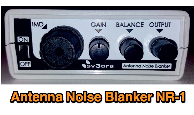 The NR-1, conceived and implemented by SV3ORA, functions as an **antenna noise blanker** to suppress impulse noise before it reaches the receiver. This device is explicitly not a QRM-eliminator or X-phaser, and it operates without requiring a separate antenna. Its primary goal is to improve receiver performance by reducing annoying noise. Documentation includes a comprehensive manual detailing its operation, alongside several videos demonstrating its functionality. The NR-1 is available for purchase directly from Elisys via their online shop. Numerous radio amateurs have reviewed the NR-1, with Pavel OK7PM highlighting significant improvements in receiver **dynamic range**. Further insights are available in an article published in the Greek magazine SVnea and through various reviews posted on eham.net.
 -
 The Lancaster & Fairfield County Amateur Radio Club is a general interest amateur radio group that offers monthly licensing exams, emergency communication activities, and social gatherings. They meet on the first Saturday of each month at 10:00 am at the Fairfield County Emergency Management and Homeland Security in Lancaster, Ohio. Meetings are public and welcome anyone interested in amateur radio, electronics, and emergency communications.