Search results
Query: 4 meter antenna
Links: 1193 | Categories: 31
Categories
- Antennas > 20M > 20 meter Dipole Antennas
- Antennas > 20M > 20 meter Vertical Antennas
- Antennas > 20M > 20 meter Yagi antennas
- Antennas > 40M > 40 meter Dipole Antennas
- Antennas > 40M > 40 meter Loop Antennas
- Antennas > 40M > 40 meter Magnetic Loop Antennas
- Antennas > 40M > 40 meter Vertical Antennas
- Antennas > 6M > 6 meter J-Pole Antenna
- Antennas > 6M > 6 meter Yagi Antennas
- Antennas > 40M > 40 meter Delta Loop Antennas
- Antennas > 40M > 40 meter Yagi Antennas
- Antennas > 6M > 6 meter Moxon Antennas
- Manufacturers > Wattmeters
- Antennas > 10M
- Antennas > 12M
- Antennas > 15M
- Antennas > 17M
- Antennas > 20M
- Antennas > 2M
- Antennas > 30M
- Antennas > 40M
- Antennas > 60M
- Antennas > 80M
- Technical Reference > Arduino
- Radio Equipment > HF Vertical Antenna > Cushcraft R8
- Antennas > Halo
- Radio Equipment > HF YAGI Antennas > Hy-Gain TH3JR
- Antennas > Morgain
- Manufacturers > Test Equipment
- Technical Reference > Test Equipment
-
-
 The document details the optimization and construction of the _Maria Maluca_ antenna, a compact 6-band (20m-6m) directional beam. It presents a comparative analysis of shortwave antenna principles, highlighting the efficiency gains achieved by using an open feeder line and tuner as a resonant unit, contrasting this with the losses associated with traps or capacitive loads in multiband antennas. The resource specifically revisits an older South American 2-element design for 10, 15, and 20 meters, applying modern NEC-based software to develop a six-band version. Performance data is meticulously tabulated, showing impedance, free space gain, gain at 12m height, elevation angle, and front-to-back (F/B) ratio for each band from 20m through 6m. For instance, on 15m, the antenna achieves 5.1 dBd free space gain and 13.72 dB F/B ratio. The construction section provides practical guidance on element assembly using aluminum pipes and hose clamps, detailing the use of a heavy-duty glass fiber reinforced polyamide rod for electrical separation and bending strength. It also specifies the use of 450-ohm _Wireman_ line CQ 552 for the transmission line. The document includes diagrams for rod fixing, an air-wound balun, and a vertical elevation diagram for the 15m band, illustrating its DX qualification. It also discusses the antenna's suitability for portable and expedition operations, noting its compact transport dimensions (max 1.50m length, 12 lb weight) and quick assembly time (under 15 minutes). The author, Dipl.Ing. Helmut Oeller, DC6NY, is identified as a source for material kits.
 -
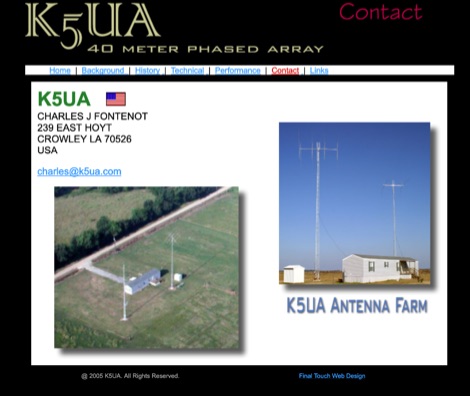 The intent of this site to share information about the design of a 40 meter horizontal phased array antenna.
 -
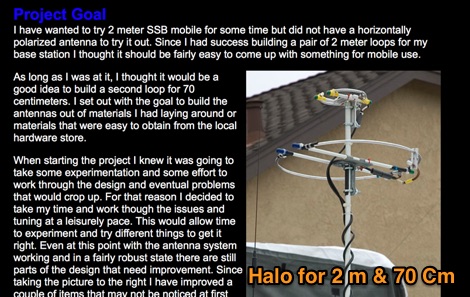 2 meter & 70 centimeter mobile halo antenna project, by N6TWW Mike Fedler
 -
-
 W1ZY's 40-meter **Moxon** antenna project details nine months of experimentation, culminating in a reversible array built from No. 12 insulated wire. The design incorporates two RF current baluns and a unique two-wire element construction, where each element consists of two parallel wires spaced 3 inches apart. The resource provides specific dimensions for the first prototype, including A=50.98', B=7.87', C=1.25', D=9.3', and E=18.42', optimized for 7.050 MHz CW operation. It thoroughly explains the construction of custom two-wire insulators from Plexiglas semi-rods and the critical pre-tensioning process required to maintain wire separation and array integrity. The author, Bill, emphasizes the antenna's exceptional receive performance, noting a 30-35 dB front-to-back ratio, which allows for significant signal rejection from the rear. While the Moxon offers 5-6 dB gain on transmit, its primary advantage lies in its ability to radically reduce rear-facing signals on receive, a characteristic Bill believes is often overlooked in transmit-focused comparisons. The guide details a flexible tuning method using removable tail-end jumpers, enabling adjustments to both tail-end and parallel dimensions without re-soldering the feed point, a technique refined over three prototypes.
 -
-
-
-

-
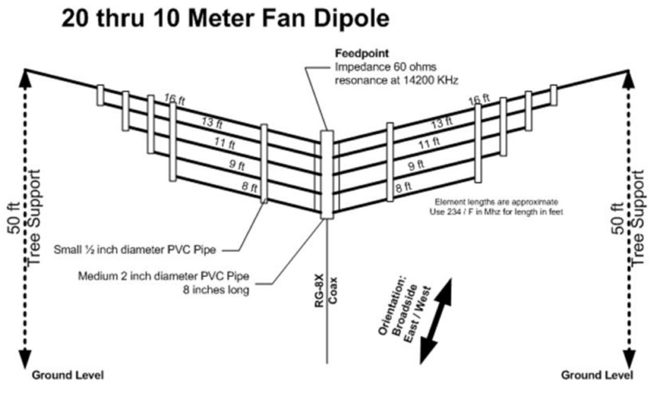 The 20 thru 10 meter dipole is constructed from stranded insulated wire available in most hardware stores. The feedpoint uses an 8 inch long section of 2 inch diameter PVC pipe. A section of wire joins the elements at either side of the feedpoint to avoid the inductance of square knots used on lower frequencies.
 -
 For radio amateurs seeking compact, directional antenna solutions, the Moxon Rectangle offers an attractive alternative to traditional two-element Yagis. This resource compiles several articles by L. B. Cebik, W4RNL, exploring the **Moxon Rectangle** design, which provides gain comparable to a full-size two-element array but with a significantly improved **front-to-back ratio** and a direct 50-Ohm feedpoint match. The collection covers both wire arrays, particularly for lower HF bands, and rotatable aluminum beam constructions, addressing various aspects of this popular antenna configuration. The articles delve into specific band applications, including designs for 10 meters, 40 meters, and 2 meters, alongside discussions on multi-banding techniques and pattern characteristics. Comparisons are drawn between the Moxon and other antenna types, such as VK2ABQ Squares, highlighting the Moxon's advantages in terms of size and performance. Practical construction notes are provided for both wire and aluminum versions, offering insights into building these antennas for different operating environments.
 -
 The article "Exploring the World of 10 Meter Beacons" by Ken Reitz, KS4ZR, provides an in-depth look at 10-meter beacon operations, focusing on their utility for propagation analysis. It details FCC Rules part 97.203 governing beacon stations, including license requirements, power limits (under 100 watts), and the specified band segment of 28.200-28.300 MHz for U.S. operations. The content highlights the diversity in beacon construction, from converted CB radios to home-brew QRP transmitters, and discusses the robust operating conditions these 24/7 stations endure. The resource presents several case studies of active 10-meter beacon operators like Ron Anderson KA0PSE/B, Domenic Bianco KC9GNK/B, and Bill Hays WJ5O/B, detailing their equipment, antenna setups, and typical signal report volumes. It also introduces the NCDXF/IARU International Beacon Project, which features 18 synchronized beacons worldwide transmitting on 28.200 MHz at varying power levels (100W, 10W, 1W, 100mW) to facilitate propagation testing. The article also covers the PropNet Project utilizing PSK31 on 28.131 MHz and the 250 Synchronized Propagation Beacon Project on 28.250 MHz. Practical advice for monitoring includes using the RST reporting method, understanding the impact of the solar cycle on 10-meter propagation, and tips for setting up a personal beacon, such as frequency selection and power output considerations. The IY4M Guglielmo Marconi Memorial Beacon Robot on 28.195 MHz is also mentioned for its automatic QSO mode. The article concludes with a list of other resources for 10-meter beacon information.
 -
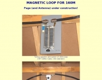 Pictures and calculated values for this home made magnetic loop antenna for the 160 meters band by HB9MTN
 -
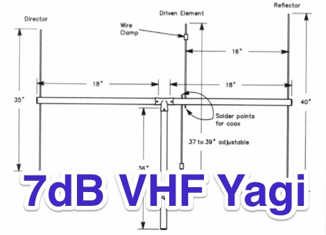 7 dB for 7 Bucks, a 2 meter beam antenna for the cost of a fast food meal!
 -

-
 Daiwa Industry, maker of power suppliers, coax cable and antenna switches, power meters, SWR meters, DC-DC converters
 -
 Yo5ofh j-pole antenna plans for 2 and 6 meters
 -
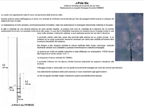 Homebrewed jpole antenna for 50 mhz by IW0BZD, include pictures and schematics, in italian.
 -
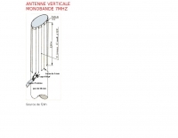 A simple drawing of a shortened antenna for 40 meters by using a PVC tube
 -
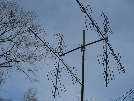 An experimental fractal Quad antenna for 10 meter band project by AG1LE
 -
 This resource presents a technical guide detailing antenna measurement theory, focusing on the fundamental electromagnetic principles governing antenna operation and characterization. It delineates the three primary spatial regions surrounding an antenna: the reactive field (0 < r < lambda/2pi), the radiating near-field (lambda/2pi < r < 2D2/lambda), and the radiating far-field (r > **2D2/lambda**). The guide defines key antenna parameters, including polarization, input impedance, VSWR, directivity, gain, efficiency, Effective Isotropically Radiated Power (EIRP), antenna noise temperature, and the G/T parameter. Radiation patterns are discussed, with examples of both rectangular and polar forms, emphasizing the determination of patterns in the far-field region for constant radial distance and frequency, typically characterized by a main beam with **3 dB** beamwidth and sidelobes. The document further elaborates on the mathematical definitions of these parameters, such as the Poynting vector (E x H*) for electromagnetic waves and the relationship between antenna gain and directivity. It also introduces related terms like mixers, which are critical components in antenna measurement instrumentation for frequency conversion (fIF = fRF +/-nfLO). The theoretical framework provided supports the scientific analysis of antenna performance, applicable to various antenna types and operational frequencies. DXZone Focus: Technical Guide | Electromagnetic Theory | Far-Field Region | G/T Parameter
 -
 A 7 elements yagi beam monoband antenna for 14 Mhz by VE3GK
 -
 Homebrew with CF300 DGMF with about .24 dBD gain
 -
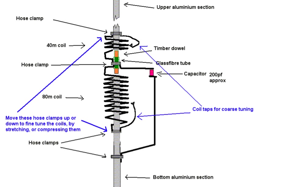 Article on the HF dual band antenna with construction details and how to add 160 meters to the HF2V
 -
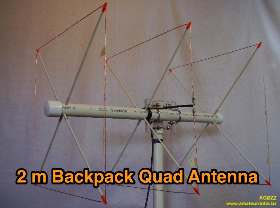 This 2 meter 3 element cubical quad antenna is small, light weight and portable. A backpack antenna that is easy to put together in just minutes and parts store inside the boom making it ready for travel or storage.
 -
 How to build a ground plane antenna for the 40 meters band in french
 -
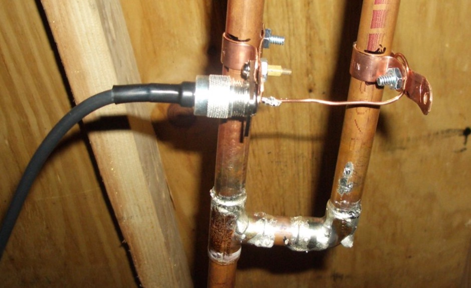 Easy home brew 2 meter copper jpole antenna build - under 20 bucks - Hits repeaters 45 miles away. Parts used bought at home depot build time 1 hour.
 -
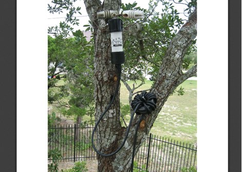 An easy to build single wire antenna for 160 and 80 meters with a better than 2 to 1 swr across the 80 meter band by K5GP
 -
 1/2wave vertical antenna for the 6-meterband and a 5/8 ground plane antenna for 50 Mhz
 -
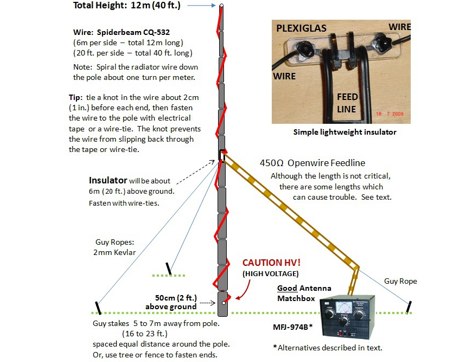 A 40 ft vertical dipole antenna that can cover HF Bands from 80 to 10 meters winding a dipole in a 12m HD telescoping fiberglass pole
 -
 The 10-meter EH Antenna document details the construction and performance of a specific EH antenna design for the 10-meter band. It describes the integration of an L+L balanced matching network, a key component for impedance transformation, and highlights the addition of a tuned coaxial trap. This trap, consisting of 8 turns of RG58 coax wound around PVC tube and resonated at 29 MHz with a 10 pF capacitor, effectively inhibits common-mode current on the feeder, stabilizing antenna tuning. The resource presents a circuit diagram in Figure 1 and assembly details in Figure 2, illustrating the use of PVC plumbing tube as host material for dipole cylinders made from recycled aluminum tubing. It also explains the fabrication of capacitor stators and slider sections from thin aluminum tubing. The author, Lloyd Butler VK5BR, discusses initial challenges with feeder interaction and how the tuned trap resolved these issues, leading to stable tuning. Limited backyard tests indicate that the antenna, with the trap fitted close to the input connector, might exhibit similar field strength for both low and high angle transmission, suggesting a potential skewing of the signal. The document references previous articles by VK5BR in "Amateur Radio" for further operational details of the matching network and trap functionality.
 -
 The Charles Gizmotchy high performance horizontal and vertical beam antennas. Two, Six, Ten and eleven meters antennas
 -
 A 144 MHz dipole antenna made from coax, PVC pipe, and aluminum foil tape
 -
 How to homebrew an hex beam antenna for 20 17 15 12 10 meters band by VA7ST
 -
 The ARRL page, titled "The HF Mobile Antenna," serves as a curated index to various _QST_ articles focusing on constructing mobile HF antennas. It presents several projects for the mechanically inclined amateur, suggesting that homebrewed antennas can achieve efficiency comparable to commercial versions. For instance, one entry details a **five-band** antenna for RVs, utilizing a fold-over Hustler 4BTV, while another describes a "Bug Catcher" design for 80 through 10 meters. Further projects include a budget-friendly $20 HF mobile antenna made from PVC and wire, covering 20 through 6 meters, and the "Alpha Special," a multiband horizontal antenna originally for 1960s station wagons, now suggested for mini-vans. The resource also addresses antenna mounting solutions specifically for travel trailers and campers, providing practical insights for those operating from recreational vehicles. Rounding out the collection are the "Connecticut Longhorn," a 75-meter horizontal whip with remote tuning, and its redesign, the "Connecticut Shorthorn," adapted for smaller vehicles post-1970s. This compilation offers a historical perspective on mobile antenna innovation and practical construction guides for various HF bands and vehicle types.
 -

-
 Constructing a compact, two-band magnetic loop antenna for HF operation, especially from constrained locations like a balcony, presents unique challenges. OK1FOU's design, inspired by DJ3RW's 50 MHz loop, addresses these by employing an unusual side-fed configuration and placing the symmetric, two-section variable tuning capacitor at the bottom of the loop, directly connected to the coax shield. The article provides specific material recommendations, including two 1-meter wooden pales and about 3 meters of thick loudspeaker cable, noting the high current (60A at 100W) in the loop. Construction steps detail forming two turns with a 5 cm gap, using a GDO to pre-tune the open loop to a frequency slightly above the desired highest band, and then integrating the tuning and coupling capacitors. For 10/14 MHz, an open loop resonance of 16-17 MHz is suggested. Practical experience with the 10 MHz band from a third-floor balcony in Prague (JO70GC) shows a 1:1 SWR across most of the band without an external ATU. While DX traffic was modest due to the urban environment, QSO examples with RA6WF, LA6GIA, G0NXA, and LZ1QK on 10 MHz are provided, demonstrating its operational capability.
 -
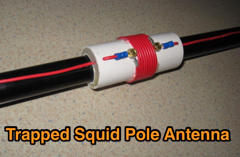 An homemade portable vertical antenna with a trap near the mid point of the main element. The trap is made with 42mm diameter PVC pipe with 9 turns of wire on it
 -
 VE7CA experiments on 160 meters band antennas, looking for better performances on reception.
 -
 Homebrew a 2 meter 1/4 wave vertical antenna for the 146 mHz ham radio band
 -
 A project for a portable antenna for amateur radio satellite reception, for 2 meters and 70 centimeters bands
 -
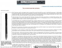 A helix will work in the normal mode when the diameter and pitch of the helix is less than 0.1 Lambda
 -
 A hand made project by I5CDF of a 2 elements Delta Loop antenna for the 40 meters band in Italian
 -
 A delta loop antenna for 17 meters band include eznec antenna model file
 -
 Demonstrates a practical modification to convert a standard G5RV antenna into a _160-RV_ for effective operation on the 160-meter band. This project addresses the challenge of achieving Top Band resonance with a common multi-band wire antenna, providing a solution for hams with limited space or resources for dedicated 160m antennas. The design utilizes a specific length of 450-ohm ladder line and a 1:1 current balun, acting as a matching section to bring the G5RV's impedance into a usable range for 1.8 MHz. The document includes a parts list, detailed construction steps, and tuning instructions, emphasizing the importance of precise measurements for the ladder line and coaxial cable sections. It also outlines the expected SWR characteristics and power handling capabilities, making it suitable for QRO operation up to 1.5 kW. The _AD1B_ design offers a straightforward approach for extending the utility of an existing G5RV.
 -
 The idea of using a low mount dipole, enhanced with reflector wires directly beneath the dipole, on the ground, appears to be a very good approach to creating an NVI specific antenna for local HF operation.
 -
 Article by Ed Bathgate, N3SDO as published in CQ VHF Magazine July, 1988
 -
 JJ0DRC's HF multi-band delta loop antenna project, initially conceived during the waning peak of Cycle 23, addresses the common challenge of achieving effective DX operation from a small residential lot in Japan. Dissatisfied with a ground plane antenna's performance in SSB pile-ups, the author sought a beam-like solution without a tower, drawing inspiration from a JJ1VKL article in CQ Ham Radio Sep. 2000. The antenna, constructed in October 2000, employs two 7.2-meter fishing rods (37% carbon fiber, reinforced with cyano-acrylate glue and aluminum tape) and 1mm enameled wire, fed by an Icom AH-4 external antenna tuner. While the exact beam pattern remains unmeasured, JJ0DRC observed a significantly higher callback rate compared to dipole antennas, particularly on higher bands. The system's circumference length of 15-20m is crucial for maintaining a good beam pattern across HF bands, though performance on lower bands like 80m, 40m, and 30m becomes less directional as the length deviates from a full wavelength. Ongoing maintenance addressed degradation issues, including aluminum tape cracking and wire breakage at connection points due to strong winds (often exceeding 10-15m/s in winter). The author reinforced rod connections with IRECTOR PIPE SYSTEM components and INSU-ROCK ties, and improved wire attachment methods using Cremona rope and epoxy bond to enhance durability.
 -
 This resource details the computer-optimized design of the _ZS6BKW_ multiband dipole, an evolution of the classic _G5RV_ antenna. It begins by referencing the original 1958 RSGB Bulletin article by Louis Varney G5RV, explaining the operational principles of the G5RV's flat-top and open-wire feedline on 20m and 40m, noting its impedance transformation characteristics for valve amplifiers of that era. The article then transitions to the rationale for optimizing the design for contemporary solid-state transceivers requiring a 50 Ohm match. The core of the project involves using computer modeling to determine optimal lengths for the flat-top and matching section, aiming for a VSWR of less than 2:1 on multiple HF bands. It discusses the process of calculating feedpoint impedance based on antenna length and frequency, referencing professional literature from Professor R.W.P. King at Harvard University. The analysis also considers the characteristic impedance (Z(O)) of the open-wire line, identifying a broad peak of adequate values between 275 and 400 Ohms. Specific design parameters for the improved ZS6BKW are presented, including a shorter flat-top and a longer matching section compared to the original G5RV, with a velocity factor of 0.85 for the 300 Ohm tape. The article confirms acceptable matches on 7, 14, 18, 24, and 28 MHz bands when erected horizontally at 13m, and also discusses performance in an inverted-V configuration, noting frequency shifts. The author, Brian Austin ZS6BKW, emphasizes the antenna's suitability for modern 50 Ohm coaxial cable without a balun.