Search results
Query: 2 meter antenna
Links: 1101 | Categories: 31
Categories
- Antennas > 20M > 20 meter Dipole Antennas
- Antennas > 20M > 20 meter Vertical Antennas
- Antennas > 20M > 20 meter Yagi antennas
- Antennas > 40M > 40 meter Dipole Antennas
- Antennas > 40M > 40 meter Loop Antennas
- Antennas > 40M > 40 meter Magnetic Loop Antennas
- Antennas > 40M > 40 meter Vertical Antennas
- Antennas > 6M > 6 meter J-Pole Antenna
- Antennas > 6M > 6 meter Yagi Antennas
- Antennas > 40M > 40 meter Delta Loop Antennas
- Antennas > 40M > 40 meter Yagi Antennas
- Antennas > 6M > 6 meter Moxon Antennas
- Manufacturers > Wattmeters
- Antennas > 10M
- Antennas > 12M
- Antennas > 15M
- Antennas > 17M
- Antennas > 20M
- Antennas > 2M
- Antennas > 30M
- Antennas > 40M
- Antennas > 60M
- Antennas > 80M
- Technical Reference > Arduino
- Radio Equipment > HF Vertical Antenna > Cushcraft R8
- Antennas > Halo
- Radio Equipment > HF YAGI Antennas > Hy-Gain TH3JR
- Antennas > Morgain
- Manufacturers > Test Equipment
- Technical Reference > Test Equipment
-
 A Mini Moxon antenna for 40 meters band project in a well done PDF document
 -
 Pictures of a 2 meter, 220, 440 copper J-Pole antennas
 -
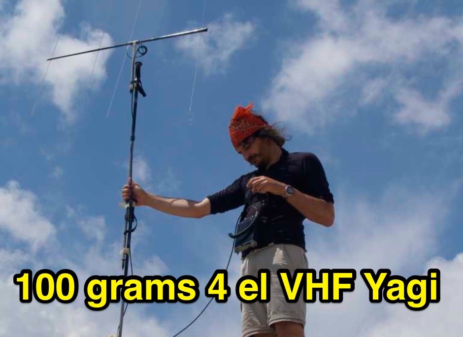 A portable VHF home-made Yagi-Uda antenna, that is extremely easy to build and very cheap. Moreover this antenna, while dismounted is just 1 meter long, and the total weight is just 100 grams.
 -
 This project outlines the construction of a 3-element reversible quad antenna specifically designed for the 40-meter band. The materials required include pushup towers, pressure-treated posts, insulated wire, and various electrical components such as relays and a balun. The construction process is straightforward, beginning with the installation of the posts in a straight line, followed by the assembly of the antenna elements and their elevation to the desired height. The antenna's design allows for directional signal reception, making it ideal for operators looking to enhance their communication capabilities on the 40-meter band. The project includes detailed instructions on tuning the antenna for optimal performance, ensuring that operators can achieve the lowest SWR possible. Additionally, the design can be adapted for other bands by extrapolating dimensions, providing versatility for amateur radio enthusiasts. Overall, this reversible quad antenna project is suitable for both beginners and experienced operators, offering a practical solution for improving signal strength and directionality in 40-meter communications.
 -

-
 A schematic design of the W3DZZ antenna in portugues with description of trap building
 -
 This resource details the construction of a versatile CW/QRSS beacon, designed around a Microchip _PIC16F84_ microcontroller. The project provides a flexible platform for transmitting either standard CW or very slow QRSS signals, making it suitable for LF, VHF, UHF, and SHF applications. It supports two distinct messages, each configurable for speed (from 0 to **127** WPM for CW, or up to **127** seconds per dot for QRSS) and repetition within a six-phase sequence. The core functionality relies on the PIC's EEPROM, which stores all operational parameters, including message content, transmission speeds, phase configurations, and relay control settings. This design allows for parameter modification directly via programming software like _ICProg_ without altering the main program code. The project includes a detailed schematic, a component list, and an explanation of the EEPROM memory mapping for messages, speeds, phase settings, and inter-phase delays. General-purpose outputs (OUT1, OUT2, OUT3) provide dry relay contacts for external control, enabling functions such as power switching, antenna selection, or frequency changes. A 'TRIGGER' input facilitates controlled starts or continuous free-run operation. Sample EEPROM configurations illustrate how to program specific beacon sequences, including message content and relay states.
 -
 AB4GX K4EAA Mononband yagi antenna for 20 Meters
 -
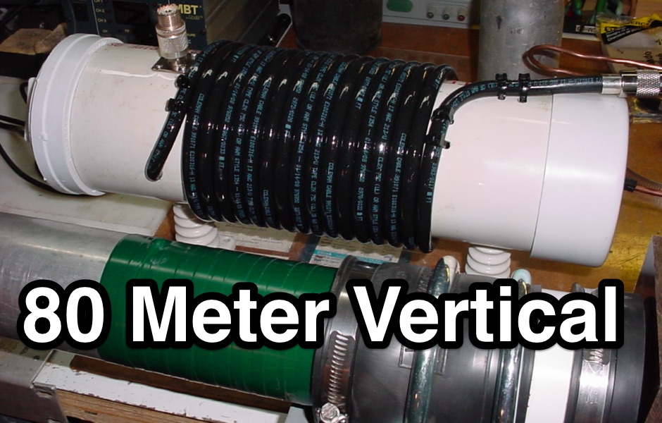
 YF1AR 80 to 40 meter vertical antenna project
 -
 An easy to build single wire antenna for 160 and 80 meters with a better than 2 to 1 swr across the 80 meter band
 -
 A two elements beam antenna tunable from 6 to 20 meters, based on the Maria Maluca antenna project by DB9EX, in german
 -
 Illustrates the specific wiring and configuration steps required to interface an SGC-230 Smartuner with an Icom IC-706 HF/VHF/UHF transceiver. The document details the necessary connections for power, control, and RF signal paths between the two devices, ensuring proper impedance matching and automatic antenna tuning functionality. It specifies the pin assignments for the IC-706's ACC socket and the SGC-230's control port, crucial for successful integration. Outlines the operational considerations for the combined system, including initial setup procedures and potential troubleshooting tips for common connectivity issues. The resource presents a clear, diagrammatic representation of the interconnections, which aids in visual comprehension of the required cable fabrication or modification. Covers the specific settings within the IC-706 menu that need adjustment to enable external tuner control, such as the 'TUNER' function and other relevant parameters. This ensures the transceiver correctly communicates with the SGC-230 for efficient antenna tuning across various amateur bands.
 -
 This is a popular antenna design as the performance is very good across the HF bands and requires little or no tuning. It is a dipole fed off center with a 4:1 current balun at the offset feedpoint. The antenna shown covers 80, 40, 20 and 10 meters with 15 meters and WARC bands
 -
 A wire yagi antenna model, easy to build, made using inverted vee elements and requiring just one support by ve3vn
 -
 A well documented article on a small magnetic loop antenna for the 40 meters band
 -

-
 A three-frequency multi-band dipole that can be extended easily to additional bands. This article includes a multiband fan-dipole antenna for 80-40-20-10 meter band.
 -
 The ZS6BKW wire antenna, a variant of the G5RV, utilizes a specific 13m (42.6 ft) length of 450-ohm window line as its matching section, feeding a 28.5m (93.5 ft) flat-top element. This design aims for lower SWR on 40m, 20m, 17m, 12m, and 10m compared to a standard G5RV, often achieving SWR values below 1.5:1 on these bands without an antenna tuner. The feedpoint impedance transformation provided by the window line allows for direct connection to 50-ohm coax on multiple bands. F4FHH's experience involved constructing the ZS6BKW and evaluating its performance against an _OCF dipole_ (Off-Center Fed) on various HF frequencies. The article includes observations on SWR readings and operational effectiveness, highlighting the ZS6BKW's suitability for multi-band operation. The antenna's overall length, including the flat-top and window line, is approximately **41.5 meters** (136 feet), making it a significant wire antenna for fixed station use. Comparative analysis with the OCF dipole provided practical insights into the ZS6BKW's advantages and limitations, particularly concerning bandwidth and tuner requirements.
 -
 An home made trapped dipole antenna for 40 and 60 meters band by 2E0HTS
 -
 Wholesale distributor of CB radios, parts, antennas, microphones, power supplies, crystals, echo boards, expanders, meters and CB accessories.
 -
-
 Homebrew a 1/4 wave 80 meter vertical using aluminium tubing
 -
 Presents the detailed construction of the _FLA25HV_ antenna, a specialized array optimized for Earth-Moon-Earth (EME) communications on the 2-meter band. This resource provides schematics and practical insights into building a high-gain antenna system capable of reflecting signals off the lunar surface, a challenging but rewarding aspect of amateur radio. It covers the mechanical and electrical considerations essential for achieving the precise pointing and signal strength required for successful moonbounce contacts, often yielding **20 dB** or more gain. Amateur radio operators pursuing EME operations require robust antenna systems and precise tracking capabilities. The FLA25HV design addresses these needs by focusing on element spacing, impedance matching, and structural integrity to withstand environmental factors while maintaining critical alignment for lunar reflections. Such systems are crucial for making contacts over distances exceeding **768,000 km**. This personal page serves as a practical guide for hams interested in constructing their own EME arrays, offering a glimpse into the technical dedication involved in pushing the boundaries of VHF/UHF propagation.
 -
 A quick vertical for 160 meters portable use
 -
 The Grid Yagi (or Grid Quad) is a high performance yagi antenna that can be built with readily obtainable inexpensive materials. Described here is a 6 element 2 meter version with a boom length of about 1 wavelength, shown
 -
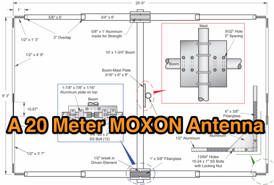 Moxons work great, and they take up less space than full size two element Yagis
 -
 A page about a Magnetic loop antenna project for the 40 meters band, includes nice pictures and history of construction
 -
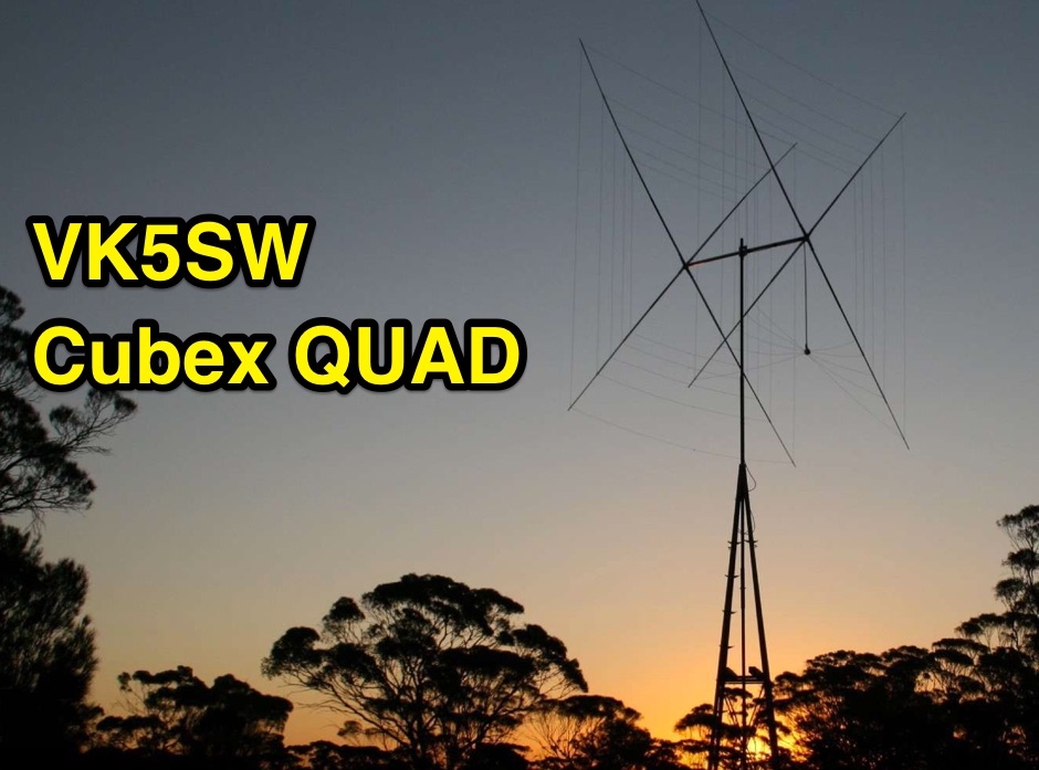 Pictures of a 2 element cubex Quad antenna at a height of 10 meter
 -
 A self supporting vertical antenna for 80 meters by W9OY include pictures and construction details
 -
-
 A popular 2 meter antenna returns in an improved, easier to reproduce form, 2008 QST article
 -
 Local and DX contacts from tight spaces, it works from 40 to 17 meters
 -

-
 An interesting article on building a 4 elements yagi antenna with gamma match for the 2 meter band. This article include two videos demonstrating assembling procedure by KG0ZZ
 -
 An 87ft inverted L portable antenna working on 80 40 30 20 15 meters band
 -

-
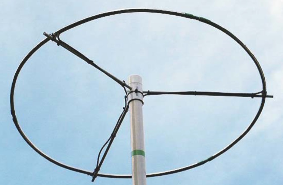
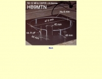 Pictures and dimensions of and HB9MTN DDRR antenna for 6 meters band
 -
 Here is an antenna for the nineties. It's strong, computer designed, and has lots of gain. It is a full size, four element beam on 10, and three elements on 15 meters
 -

-
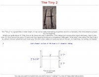 The "Tiny 2" is a great little 2 meter beam. It has some really interesting properties and it is a fantastic first time antenna project for the beginner.
 -
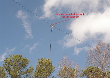
 A half-sized Hentenna designed for unique performance in compact spaces. Initially built in 2003 for monitoring a local 146.97 MHz repeater from a basement shop, the antenna proved highly effective, operating at just 200mW. In 2005, it was adapted for use in a challenging river-bottom location, delivering reliable performance on a 2-meter band with 5W. Despite its compact size, the Forktenna demonstrated excellent results compared to a full-sized Hentenna, making it an intriguing option for many hams.
 -
 A 40-meter antenna that provides good local and regional coverage during the day and good DX capability at night
 -
 This note looks at the antenna and antenna model for the 40 meter Moxon Yagi designed by Dave Leeson, W6NL. The performance of the antenna, through the model, will be explored in several typical settings.
 -
 A multiband wire antenna with a twinlead feedline that can be easily tuned in several bands, witha 33 ft per leg you can have a 40 to 10 meters band coverage
 -
 An homebrew crossed Yagi antenna for two meters band based on DK72B design with pictures, detailed description and tricks by Barry Zarucki M0DGQ
 -
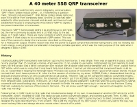 This transceiver was conceived as a power-efficient, small, lighweight unit to be carried in the backpack, along with antenna and battery.
 -
 Operating a ZS6BKW antenna often involves understanding its lineage from the _G5RV_ design, with specific modifications by ZS6BKW to optimize performance on several bands. Through computational analysis and field measurements, the antenna's dimensions were refined to allow operation on 10, 12, 17, 20, and 40 meters without an antenna tuner. For 80, 30, and 15 meters, a tuner is necessary, though efficiency on 30 and 15 meters is noted as not particularly high. The physical configuration consists of two 13.755-meter radiating elements fed by a 12.20-meter section of 450-ohm ladder line. Tuning the antenna on the 20-meter band is critical, and any deviation in the ladder line's characteristic impedance necessitates recalculating the element lengths. The design is also referenced in the 12th edition of _Rothammel's Antennenbuch_, page 219. Proper common mode current suppression is crucial at the transition from ladder line to coaxial cable. This can be achieved with a common mode choke, such as several turns of coax wound into a coil or over a ferrite toroid like an Amidon T130. While a 1:1 balun is an option, it may introduce issues.
 -
 A home made vertical polarized moxon antenna for 144 MHz, includes dimensions, antenna pattern, SWR and antenna gain plots by WB5CXC
 -
 40 meter vertical antenna construction, a shortened easy-to-build vertical, with no-radials, made from surplus military camouflage poles
 -
 A vertical antenna specifically designed to work with the 80 meter CW beacon keyer