Search results
Query: frequency
Links: 713 | Categories: 31
Categories
- Ham Radio > Band Plans > Frequency coordination
- Manufacturers > Test Equipment > Frequency Counter
- Technical Reference > Frequency Counter
- Software > Low Frequency
- Technical Reference > Radio Frequency Interference
- Manufacturers > Antenna Analyzers
- Technical Reference > Calculators
- Software > Databases
- Technical Reference > DTMF
- Technical Reference > Duplexers
- Radio Equipment > HF Transceivers > Elecraft K3
- Manufacturers > Antennas > VHF UHF Microwave > Ground Plane Antennas
- Operating Modes > HF Operations
- Propagation > MUF Indicators
- Radio Scanning > Nature
- Technical Reference > Radio Frequency Interference > Noise Reduction
- Radio Scanning > Police Scanning
- Radio Scanning
- Radio Scanning > Radio Scanning Reference
- Operating Aids > Radio Spectrum
- Radio Scanning > RailRoad
- Ham Radio > Resources
- Technical Reference > RF Design
- Manufacturers > Antennas > VHF UHF Microwave > Satellite antennas
- Manufacturers > Test Equipment > Spectrum Analyzers
- Operating Modes > SSTV
- Propagation > Sunspots
- Shortwave Radio > SWL Resources
- Shortwave Radio > Broadcasters > Time Signal Radios
- Manufacturers > Software Defined Radio > Upconverters
-
 A very popular method of making a short dipoles resonate at a given frequency. This type of antenna is suitable for single band, narrow bandwidth use.
 -
 Constructing a dip oscillator provides radio amateurs with a fundamental piece of test equipment for resonant circuit analysis. This particular design, adapted by VK3YE from a concept by _Drew Diamond VK3XU_, details a practical build using readily available components. The unit incorporates four plug-in coils, covering a frequency range from **2.6 MHz to 55 MHz**, mounted on 5-pin DIN plugs for versatility. A salvaged two-gang air dielectric variable capacitor, fitted with a vernier reduction drive, serves as the tuning mechanism, with the smaller gang optimizing bandspread at higher frequencies. In practical application, the dip oscillator is used by setting the meter needle to approximately two-thirds scale. When the instrument's coil is brought near a tuned circuit under test, a noticeable dip in the meter reading indicates resonance. This allows for precise measurement of resonant frequencies in antennas, filters, and other RF circuitry, proving invaluable for homebrewing and troubleshooting. The design emphasizes short wire runs for stable operation, particularly at the higher end of its operational range.
 -
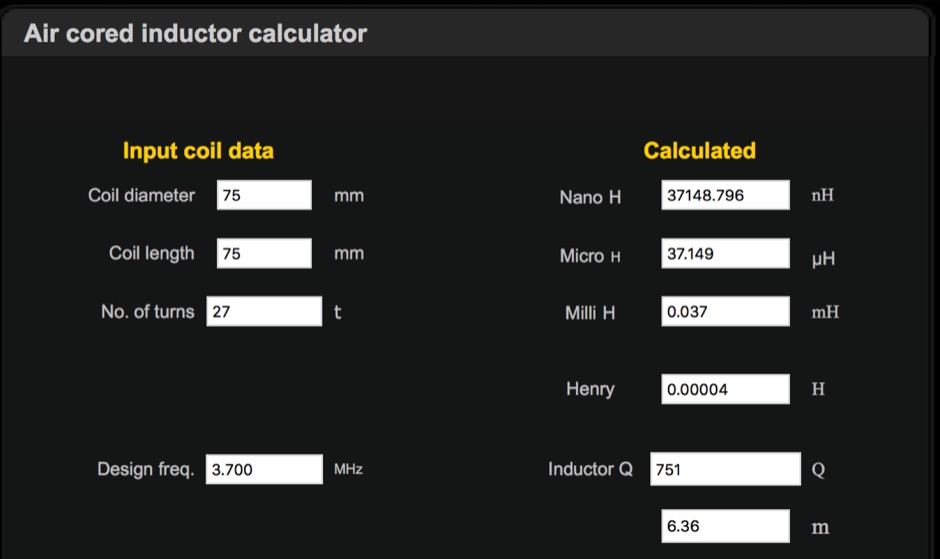 Online calculator for Input coil data, LC Resonant Frequency and L match
 -
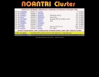 The Noantri WebCLX presents real-time DX spots, including frequency, DX callsign, country, and comments, facilitating active DXing and contesting. It operates as a web-based cluster, offering an alternative to traditional Telnet clusters for accessing spotting data. The interface displays current UTC, allowing operators to track propagation and activity across various amateur bands. This service is maintained by the _Noantri DX Group ARI Roma_, indicating its origin within the Italian amateur radio community. It supports the dynamic exchange of DX information, crucial for operators seeking new entities or participating in competitive events. Key features include the display of spots for modes like FT8, and it functions as a DXSpider-based system, providing a robust platform for **DX spotting** and **propagation analysis**.
 -
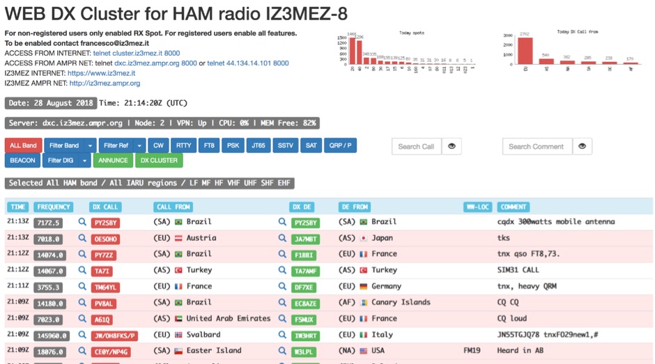 The IZ3MEZ Web DX Cluster presents real-time amateur radio DX spots across 20 distinct frequency bands, spanning from **LF (2190m)** at 135.7 kHz up to **SHF (QO-100)** at 10499 MHz. It displays the DX callsign, frequency, DXCC entity, spotter callsign, and spotter DXCC entity, along with any accompanying comments. The cluster also lists various operating modes such as CW, RTTY, FT8, FT4, FT2, PSK, and SSTV, and supports special operating activities like QRP/P and specific award programs including IOTA, POTA, SOTA, WCA, and JOTA. The cluster's interface provides a dynamic feed of the latest 50 spots, continuously updated with precise timestamps. It offers direct **Telnet protocol** access for users preferring a command-line interface, with configuration instructions provided. The resource also integrates with other spotting networks like RBN and PSK Reporter, enhancing its utility for DXers and contesters seeking propagation information and activity monitoring across a broad spectrum of amateur radio frequencies.
 -
 Naptech buys and sells quality test equipment from hp, tektronix, including spectrum analyzers & peripherals, oscilloscope, frequency counters timers, signal generators, multimeters & voltmeters, RF & power meters, microwave amplifiers
 -
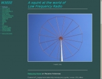 A squint at the world of LF This website was initially thrown together to provide ready availability to data being collected from the measurement of a transatlantic LF (Low Frequency) path.
 -
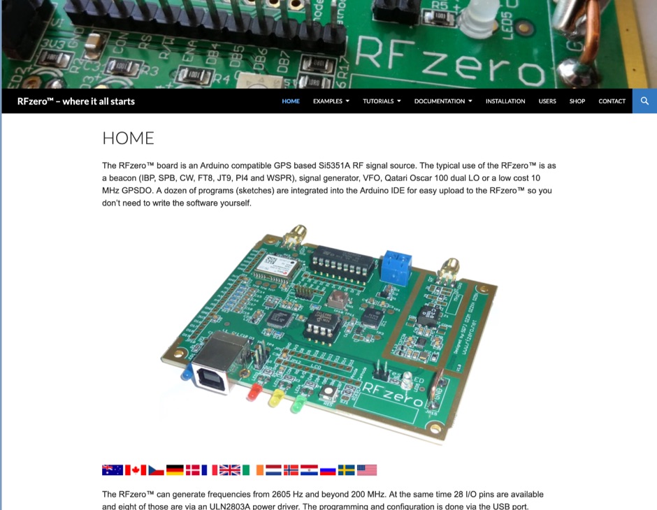 The RFzero is a multi function signal platform developed for radio amateurs who wants to extend the Arduino skills in combination with RF. The RFzero board is largely compatible with the Arduino Zero and Arduino M0 boards, however, it has been carefully designed for flexible use in RF applications and with attention to the frequency spectrum and stability performance.
 -
 Homebew a frequency marker by 7N3WVM
 -
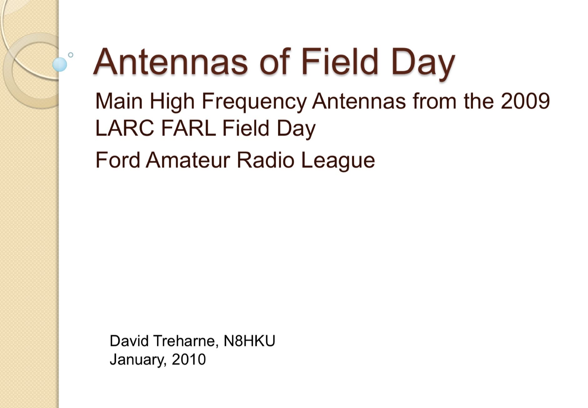 Main High Frequency Antennas from the 2009 LARC FARL Field Day, Ford Amateur Radio League. A document comparing antenna performances and flexibility among a G5RV an Carolina Windom and a Cushcraft R7 vertical antenna.
 -
 Spectrum manufactures very high-performance, low-cost, GPS-disciplined time and frequency reference standards for industry, scientific, calibration, broadcast and amateur operators.
 -
 The Utility DXers Forum (UDXF) provides a centralized platform for exchanging news and information concerning utility radio stations and signals operating within the 0 to 30 MHz spectrum. It specifically excludes broadcasting, pirate, and amateur radio transmissions, concentrating instead on a diverse array of other signals. The resource details the types of stations covered, including maritime coastal and ship stations, aeronautical ground and aircraft communications (voice, HFDL, Selcalls, Volmet), military operations, various beacons (NDB, driftnet, propagation, pirate, high-frequency), fax transmissions, numbers stations, diplomatic communications, clandestines, and other unusual signals. Further content addresses radar systems such as Over-the-Horizon, Ocean Wave, and CODAR, alongside ionosondes, chirpsounders, ALE-systems, Selcall-systems, and tone calls. Experimental stations and standard frequency and time stations are also within its scope. The forum also acknowledges utility radio-related amateur events like the International Lighthouse Weekend and Night of Nights, providing a broader context for listeners. The site offers sections for modes, hardware, software, a utility radio archive, digital BC & HF conditions, and a utility radio club archive, along with QSLs and pennants.
 -
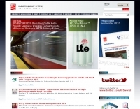 Examines Radio Frequency Systems (RFS), a manufacturer specializing in high-performance cable solutions for diverse communication infrastructures. The company, with over 120 years of heritage, focuses on designing and producing robust, long-life connectivity systems, including _low loss foam dielectric RF cable_ and _premium radiating cable_. RFS's product range supports critical applications in cellular networks, microwave antenna systems, and specialized installations within buildings and tunnels. The resource highlights RFS's commitment to innovation, addressing emerging industry standards like _FRMCS_ for railway communication and advanced fiber solutions for data centers. It also details the company's manufacturing capabilities in Hannover, Germany, emphasizing the quality and reliability associated with _Made in Germany_ products. The content covers various connectivity landscapes, from urban solutions for connected cities to private 5G credentials and future plans. Specific product categories include _fiber, power & hybrid cable_, and _low loss high power air dielectric RF cable_, showcasing their broad portfolio for complex RF environments.
 -
 On March 27, 2017, the FCC adopted final rules for the USA 630-meter band, detailed in Report and Order FCC 17-33, which required PLC coordination with the Utilities Telecom Council before amateur operations could commence. This resource documents the WD2XSH experimental group's activities, including authorized stations, band plans, and frequency assignments within the 465-515 KHz range, with many stations operating between 495-499 KHz and 501-510 KHz. The site also highlights the WRC-12 decision on February 14, 2012, which granted a new **7-kilohertz-wide** secondary allocation between _472-479 kHz_ for the Amateur Radio Service worldwide. The group's efforts included operating with a maximum ERP of **20 Watts** across 45 stations in the continental USA, Alaska, and Hawaii, using emission modes such as CW, PSK-31, FSK-31, and MSK-31. The site provides links to download FCC 17-33 in PDF and DOCx formats, and offers a station location map, a list of stations by callsign and frequency, and an archive of news updates. Reception reports for any 600-meter station are encouraged to help the amateur radio community understand propagation and repeatability on this challenging band.
 -
 The 2200-meter band (135.7-137.8 kHz) presents unique challenges for amateur radio operators due to its narrow 2.1 kHz bandwidth, low signal levels, and high noise. W1TAG explores various transmission modes suited for this demanding environment, highlighting that traditional voice modes like SSB and AM are impractical. Plain old CW serves as the baseline, demonstrating effectiveness across different modes, though signal-to-noise ratio (SNR) significantly limits practical speeds. The article notes that reducing CW speed below 5 WPM can improve copy, especially with computer-aided spectrum analysis software capable of decoding signals too weak for human ear reception. QRSS, or "CW sent slowly enough that speeds are best expressed in seconds per dot," is a key mode for LF work, with examples ranging from 3 seconds/dot to extreme 240 seconds/dot transmissions. _Argo_ by I2PHD is mentioned as a simple program for QRSS, enabling reception of signals like BRO, a Part 15 beacon, at a distance of **1100 miles**. Other modes discussed include Dual Frequency CW (DFCW), which uses frequency shifts to distinguish dots and dashes, and Binary Phase Shift Keying (BPSK), a phase modulation technique employing 0 to 180-degree phase flips. WOLF (Weak-signal Operation on Low Frequency), a specialized BPSK form by KK7KA, encodes 15-character messages into 960-bit packages, taking 96 seconds to transmit, and has demonstrated successful reception over **672 seconds** for a message from a 1-watt beacon. Further modes include PSK, FSK variations like JASON and MSK, and graphical modes such as Hellschreiber and Chirped Hell. The article concludes with a practical chart comparing the time required to send a simple message like "WD2XES FN42CH " across these diverse LF modes, offering valuable insights for operators planning contacts on the low bands.
 -
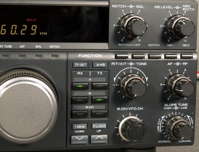 TS-850 is not much effective on AM since it does produce fairly clean audio, however while it does noticeably improve low-end frequency response
 -
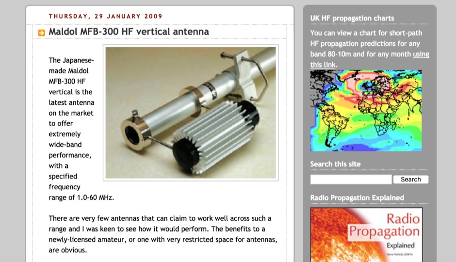 The Japanese-made Maldol MFB-300 HF vertical antenna offer extremely wide-band performance, with a specified frequency range of 1.0-60 MHz.
 -
 LA6EIA Ole's DX-blog details shortwave listening (SWL) and amateur radio DX operations from Norway, providing insights into propagation conditions and station reception. The blog frequently features specific reception reports, often including details such as frequency, mode, and signal strength, alongside observations of various broadcast and utility stations. It documents the author's personal experiences in chasing DX, offering a practical perspective on radio propagation and equipment performance. The content includes logs of received stations, sometimes accompanied by audio clips or screenshots of waterfall displays, illustrating successful decodes or strong signal captures. This resource presents a chronological record of DX achievements and challenges, reflecting the dynamic nature of radio propagation across different bands and times. The blog distinguishes itself by its focus on real-world SWL and amateur radio DXing from a Nordic QTH, offering a unique regional perspective on global radio phenomena. It serves as a personal journal of radio exploration, highlighting specific callsigns, frequencies, and operational details encountered during DX sessions.
 -
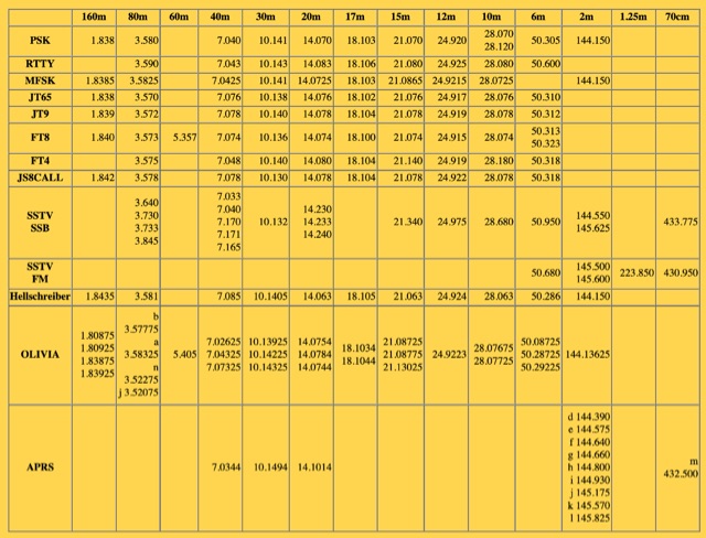 A summary of common calling frequency for each digital mode on that band.
 -
 An exaustive document on frequency multipliers with a particular attention on ways to generate high frequency signals for microwave
 -
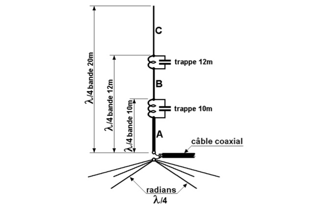 This antenna is an omnidirectional and multiband and it is well suited for DX enthusiasts with limited space. Each of the parallel circuits (trap) behaves like an isolator on its resonant frequency.
 -
 Amateur radio repeaters extend communication range for mobile and remote stations by retransmitting signals on a different frequency, often for emergency communications. The resource details various repeater bands, noting that 2 meters and 70 cm are primary for activity, with 10-meter repeaters offering potential national and overseas coverage. It specifies **18 channels** on 6 meters and **31 channels** on 2 meters, along with a new 70 cm offset of _7 MHz_ adopted in 2015. The content explains how repeaters can be linked via dedicated transmitters/receivers, landlines, or Internet VoIP systems like _IRLP_ and Echolink, enabling global connections. It also describes simplex gateways for multi-band operation and the use of CTCSS subaudible tones for access control and interference mitigation. The document highlights specialized repeaters for modes beyond voice, such as SSTV and ATV, particularly on 70cm and higher bands. Operational guidelines for efficient and courteous repeater use are referenced, along with links to Australian repeater listings and band plans.
 -
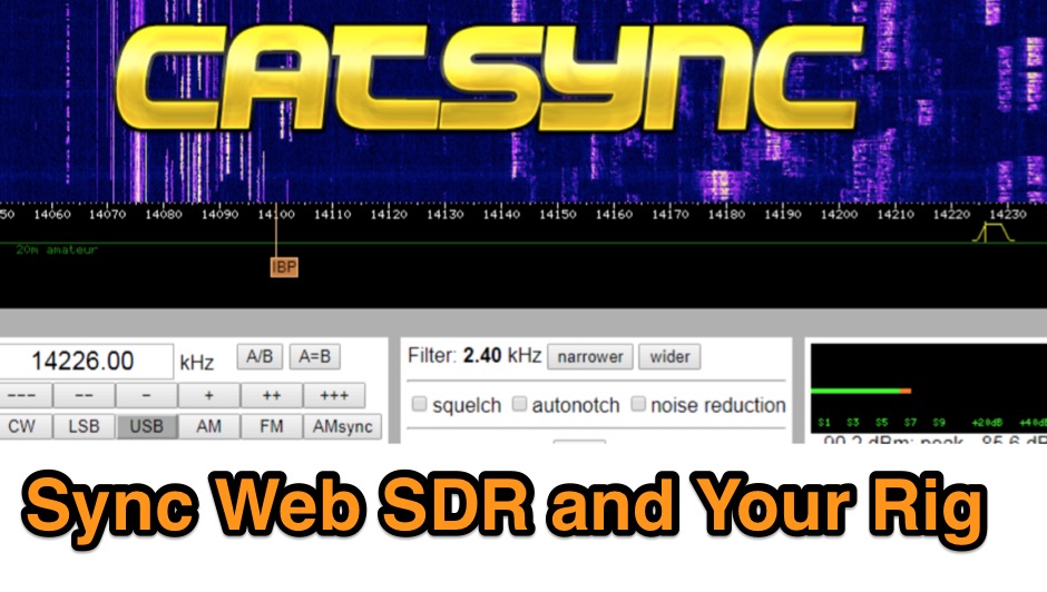 CATSync V1.30 integrates OpenWebRX support, expanding its capability to synchronize a local amateur radio transceiver's CAT control with a broader range of public WebSDR receivers. The software facilitates real-time frequency tracking, allowing the operator to adjust their physical rig's VFO and observe the connected WebSDR instantly follow the tuned frequency. This functionality is crucial for remote listening, signal comparison, and verifying propagation conditions across different geographic locations using a familiar hardware interface. The application supports both the classical WebSDR interface and KiwiSDR platforms, providing a consistent control experience across various online SDR deployments. It bridges the gap between local station operation and the vast network of globally distributed software-defined radios, offering a practical tool for DXers and contesters. CATSync is designed for Windows and Linux environments, with Android compatibility noted, making it accessible to a wide user base seeking to leverage WebSDR resources with their existing station setup.
 -
 This resource provides a discussion group platform for amateur radio operators interested in APRS within Argentina. It facilitates technical discussions, sharing of operational experiences, and coordination among users of the Automatic Packet Reporting System in the region. The group serves as a central point for exchanging information on local digipeater networks, IGate deployments, and mobile tracking applications, covering both hardware and software aspects relevant to APRS implementation. The forum enables members to post questions, offer solutions, and disseminate news related to APRS activities specific to Argentina, fostering a community-driven approach to problem-solving and knowledge transfer. It supports the collaborative development and maintenance of the APRS infrastructure, allowing for real-time interaction on topics such as frequency usage, network topology, and integration with other amateur radio services.
 -
 The National Frequency Coordinator\'s Council (NFCC) is an organization comprised of and representing amateur radio frequency coordinators of the United States.
 -
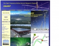 A Scientific endeavor aimed at studying the properties and behavior of the ionosphere.
 -
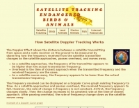 The Doppler Effect allows the distance between a satellite transmitting from space and a radio receiver on the ground to be measured by observing how the frequency received from the satellite transmitter changes as the satellite approaches, passes overhead, and moves away.
 -
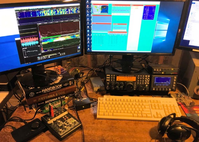 This article will explain a few of the ways author use an external SDR and Linrad to enhance his K3 experience. Linrad is one of many available SDR receiver programs. The same could be done with any radio that lets you access its IF frequency output. Article from NCJ Nov Dec 2019
 -
 RF Safety reource page with links and more documentation on radio frequency safety
 -
 Tabor electronics produces high-end function generator, universal counters/timers, synthesizers, pulse, function and arbitrary waveform. Frequency counters
 -
 High Frequency Expermental Beacon "WV". The Beacon operates on the frequency of 13.55567mhz. This Beacon is very low power. It operates under Part 15 of the FCC Rules and Regulations. It transmits with only 1.5 milliwatts of power
 -
 Over 1900 ARISS school events have been conducted since 2000, facilitating amateur radio contacts between students and ISS crew members. This resource details the Amateur Radio on the International Space Station (ARISS) program, outlining scheduled contacts, operational procedures, and application processes for educational institutions worldwide. It lists specific upcoming contacts, such as those with Lewis Center for Educational Research in California and Vauban, Ecole et Lycée français de Luxembourg, typically operating on a 145.800 MHz downlink frequency. The content also provides crucial guidelines for radio amateurs, emphasizing the importance of not interfering with scheduled school contacts and utilizing the crossband repeater for general QSOs when available. It clarifies crew availability for casual contacts, noting that astronauts are usually free during personal time, approximately one hour after waking and one hour before sleeping, and often on weekends. Constraints on scheduling, such as avoiding EVA weeks and specific crew rest periods, are also detailed. Furthermore, the resource includes historical statistics on direct versus telebridge contacts, QSL information, and links to related ARISS, AMSAT, ARRL, and NASA websites. It also provides information on applying to host an ARISS contact for schools and youth organizations in various regions, including the United States, Europe, Africa, the Middle East, Canada, Central and South America, Asia, and Australia.
 -
 An Google Maps interactive layer showing Australian amateur radio repeaters. You can navigate and zoom as required and click on a repeater-site icon to display frequency, ctcss and other details and notes for that repeater.
 -
-
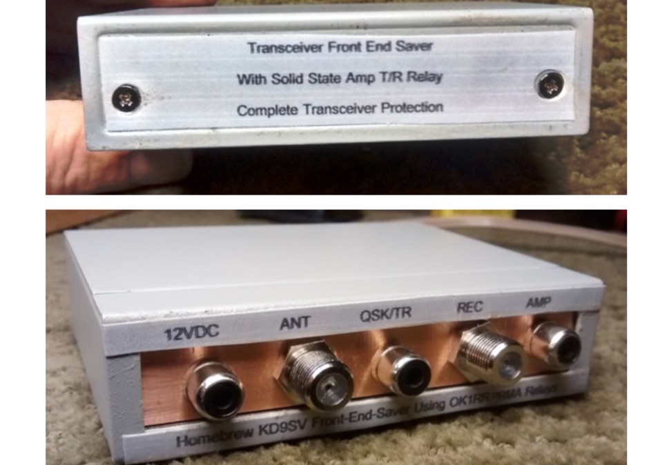 Homemade RF limiter project, to protect the K3 receiver front-end for high radiofrequency based on the original KD9SV project.
 -
 Cmpter Electronics specializes in the design and manufacturing of RF coaxial connectors, RF adapters, and RF cable assemblies, serving diverse applications across datacom/telecom, automotive, instrumentation, aerospace, and defense sectors. Their product line includes RF coaxial terminations, attenuators, and waveguide to coax adapters, catering to specific needs in radio frequency systems. The company also offers precision adapters and connectors, alongside glass beads and test cable assemblies, indicating a focus on high-quality components for demanding RF environments. Their resource center provides valuable information, including an "RF Made Simple" section and a product catalog for download, which assists engineers and technicians in selecting appropriate components. The product named system helps in identifying specific parts, streamlining the procurement process for complex RF solutions. With a comprehensive range of RF coaxial cables and related tools, Cmpter Electronics positions itself as a key supplier for critical infrastructure requiring reliable signal integrity. Their offerings support a broad spectrum of RF applications, from basic connectivity to advanced test setups.
 -
 Constructing a multi-band fan dipole for HF operation presents unique challenges, as VE2XIP demonstrates through his 2012 project to replace an existing commercial antenna. He details the process of calculating wire lengths using the 468/frequency formula, emphasizing the critical importance of equal leg lengths for each dipole element. The author shares practical insights gained from building at ground level, noting how elevation impacts resonant frequency and SWR, particularly for lower and higher bands. VE2XIP's experience highlights the iterative nature of antenna tuning, starting with the lowest frequency band (80m) and working upwards. He provides a specific example of trimming calculations and offers a clever tip for accurate wire removal. The article also touches on the mechanical aspects, such as dowel spacing for wire support and the benefits of a pulley system for repeated raising and lowering during the tuning process. Field results showed significant performance gains over the previous Alpha-Delta DX LB Plus, with **20 dB over 9** signal reports on 80m compared to 57. The project cost around **$100** for hardware, proving a cost-effective alternative. The author also discovered a bonus 6m capability and achieved an inverted-V _obtuse angle_ of approximately 115 degrees, contributing to a surprisingly stealthy installation.
 -
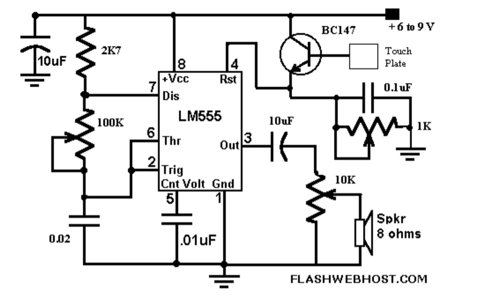 The _Touch CPO_ circuit offers a unique method for Morse Code practice, eliminating the need for a physical key. It leverages the versatile IC555 timer, configured as an astable multivibrator, to generate an audio tone. Users can adjust the tone's frequency by manipulating a 100 K variable resistor connected between pins 7 and 6 of the IC555, providing flexibility in the practice experience. Volume control is achieved via a 10 K variable resistor, while a 1 K Ohms preset at pin 4 of the IC555 allows for fine-tuning the touch plate's sensitivity. The design connects the touch plate to the base of a BC147B transistor, a configuration noted for its flexibility regarding the length of wire between the transistor and the touch plate. The author's prototype successfully used a 9 cm wire with a 3 x 6 cm aluminum plate. This project also suggests an alternative application as a touch-operated doorbell, demonstrating the circuit's adaptability. The design emphasizes simplicity and ease of construction, making it accessible for hams interested in DIY electronics.
 -
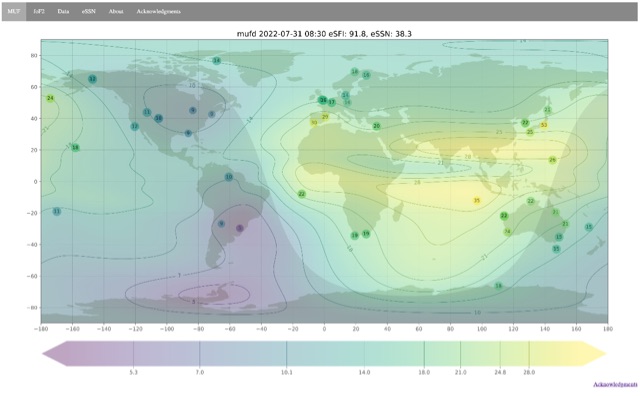 Ionospheric propagation maps MUF and critical frequency
 -
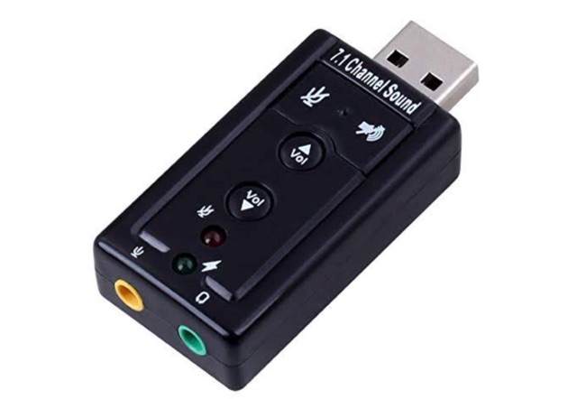 This project is a USB Audio, Serial and PTT interface for rigs that does not directly support digital modes provided by applications such as FLDIGI, WSJT-X and JS8CALL. Plug these interface devices into your Windows or Linux laptop or Raspbian Raspberry Pi and you can send and receive digital tones to/from your rig and automate the frequency and mode control and PTT control.
 -
 British Columbia Frequency Modulation Communications Association
 -
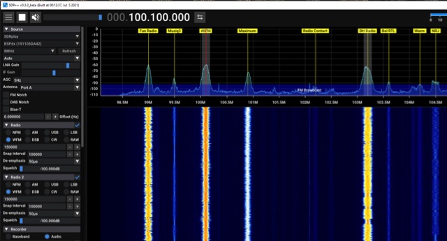 SDR++ is a cross-platform, open-source SDR software designed for minimal bloat and ease of use, supporting Windows, Linux, macOS, and BSD operating systems. It incorporates multi-VFO capabilities and offers extensive hardware compatibility through both _SoapySDR_ and dedicated modules. The software features SIMD accelerated DSP for efficient signal processing and provides full waterfall updates when possible, which enhances signal browsing. Its modular design facilitates the development of custom plugins, allowing users to extend its functionality. The application's focus on a bloat-free architecture and user-friendly interface aims to simplify the experience of working with Software Defined Radios. The full waterfall update mechanism is particularly beneficial for visualizing and identifying signals across a wide frequency spectrum, improving operational efficiency for radio amateurs. The modular plugin system enables community contributions and specialized enhancements, making _SDR++_ adaptable for various amateur radio applications, from general listening to specific digital mode decoding.
 -
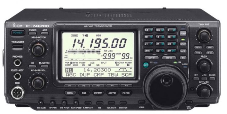 Frequency calibration is a user adjustment on the rear panel. Learn how to calibrate the IC-746 Pro.
 -
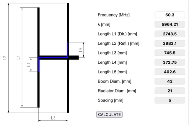 Online HB9CV antenna calculator, accept as input the desired resonating frequency and provides dimensions for spacing and length of each element, including boom and radiator diameter.
 -
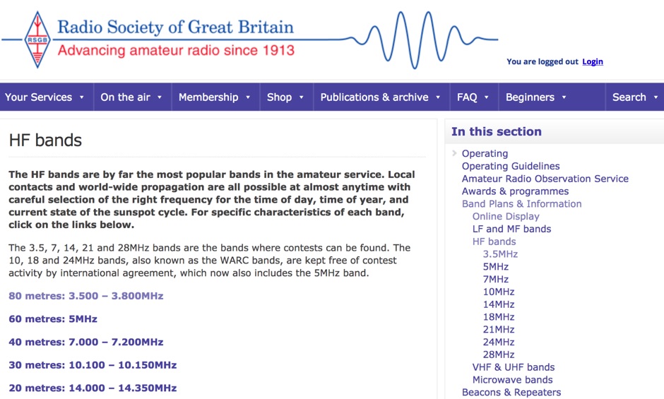 A review of the HF ham radio bands, considere by far the most popular bands in the amateur service. HF bands offer local QSOs and world-wide propagation are all possible at almost anytime with careful selection of the right frequency for the time of day, time of year, and current state of the sunspot cycle.
 -
 Operating in the **microwave** spectrum, Response Microwave, Inc. specializes in the design and manufacturing of RF and microwave signal processing components and subsystems. The company's product line encompasses a wide array of offerings, including Connectivity Series components, rotary joints, phase shifters, cable assemblies, surge protectors, terminations, Hybridline/Couperline products, circulators/isolators, directional couplers, quadrature hybrids, attenuators, custom assemblies, filters/diplexers, DC blocks & bias tees, power dividers/combiners, laser diodes & drivers, high-frequency connectors, and precision test accessories. This extensive catalog supports various applications requiring precise signal manipulation and transmission at elevated frequencies. The resource provides access to a comprehensive product catalog and a dedicated connector catalog, detailing specifications for components like **high-frequency connectors** and test cables. While specific performance data or comparative analyses are not directly presented on the main page, the breadth of products indicates a focus on providing foundational building blocks for microwave systems. The company emphasizes customer service and aims to be a reliable source for RF/Microwave/Optics product requirements, serving a growing customer base with its specialized component offerings.
 -
 Sixty-meter repeaters typically use a 1 MHz frequency separation between input and output, while 2-meter repeaters commonly employ a **600 kHz** split and 70-centimeter repeaters use a **5 MHz** offset. This article details the fundamental technical principles of amateur voice repeaters, explaining how they extend VHF/UHF communication range by receiving on one frequency and simultaneously retransmitting on another. It covers essential components such as receivers, transmitters, filters, and antennas, often situated on elevated locations for optimal coverage. The resource delves into the critical challenge of _desensing_—where the repeater's strong transmit signal overpowers its own receiver—and the engineering solutions employed, including antenna separation and the use of high-Q cavity filters. It also explores various control and timing systems, from basic squelch activation to more sophisticated microcontroller-based boards that manage functions like voice identification, time-out timers, and fault protection. Different access methods are discussed, including open access, toneburst, CTCSS subtone, and DTMF, each offering distinct advantages for managing repeater usage and mitigating interference. Furthermore, the article examines repeater linking, both conventional RF methods and modern internet-based solutions, highlighting how linking expands coverage and promotes activity across multiple repeaters or bands. It introduces less common repeater types such as 'parrot' repeaters, which use a single frequency and digital voice recording, and linear translators, capable of relaying multiple signals and modes simultaneously across different bands, often found in amateur satellites.
 -
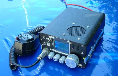 This article describes the construction of a high performance transmitter and receiver for SSB (voice) communication covering the 14MHz (20 meters) high frequency amateur radio band with output range 15 to 20 watts and a top audio sound quality both on transmit and receive.
 -
 Offer a Direct Digital VFO Kits (variable-frequency oscillator) using the Analog Devices AD9951 by WA1FFL
 -
 High power, UHF, L-band, S-band, C-band, microwave frequency amplifier and oscillator devices, pulsed, CW, fixed-tuned, or tunable devices in the range of 600 MHz to 2000 MHz