Search results
Query: project design
Links: 296 | Categories: 17
Categories
- Software > Circuit Design
- Technical Reference > 3D Printed Projects
- Software > Front Panel Design
- Software > PCB Design
- Antennas > 20M
- Antennas > 2M
- Manufacturers > Arduino
- Manufacturers > Front Panel
- Technical Reference > Keyers
- Antennas > Log Periodic
- Antennas > Receiving
- Technical Reference > Receivers > Regenerative Receiver
- Antennas > Resonant Feedline Dipole
- Antennas > Satellite
- Antennas > Traps
- Antennas > Vertical
- Antennas > VHF UHF
-
 The W5GI Mystery Antenna is a versatile multi-band wire antenna designed for amateur radio operators. It covers frequencies from 80 meters to 6 meters, making it suitable for a wide range of operating conditions. The antenna features a low feed point impedance, allowing for easy matching with most radios, whether or not an antenna tuner is used. Its construction is straightforward, requiring only two vertical supports approximately 130 feet apart, making it ideal for hams without towers. Users have reported excellent performance, particularly on the 20-meter band, where it outperforms similar designs like the G5RV. This antenna is unique in its design, incorporating three half waves in-phase on 20 meters, resulting in a six-lobe radiation pattern. Despite its effective performance, the antenna is challenging to model, which adds to its mystique. The W5GI Mystery Antenna has gained popularity among amateur radio enthusiasts worldwide, with many users praising its ease of construction and effectiveness. Whether you're a beginner or an experienced operator, this antenna offers a fun and rewarding project that can enhance your HF capabilities.
 -
 This guide provides step-by-step instructions for constructing a tin can waveguide antenna, commonly known as a cantenna, for enhancing WiFi signal range. The project is budget-friendly, costing under $5, and utilizes easily accessible materials like a food can and basic electronic components. The design is suitable for 802.11b and 802.11g wireless networks, operating within the 2.4 GHz frequency range. To start, gather the necessary parts including an N-Female chassis mount connector, nuts, bolts, and a suitable can. The assembly process involves drilling holes in the can for the connector and mounting the probe. The guide emphasizes the importance of can dimensions and placement for optimal performance, encouraging experimentation for best results. This project is ideal for amateur radio operators and DIY enthusiasts looking to improve their wireless connectivity without significant investment. Safety precautions are advised, as the author does not hold electrical engineering credentials. Users are encouraged to take responsibility for their equipment and ensure proper assembly. With this simple yet effective antenna, users can extend their WiFi coverage and enjoy enhanced connectivity.
 -
 This resource provides comprehensive instructions for constructing a 2 element quad antenna specifically designed for the 10, 12, and 15 meter bands. The antenna features a diamond configuration, which offers improved gain compared to a square configuration. The author shares insights into the materials used, including a square-aluminum boom and bamboo poles, along with construction techniques that ensure durability and optimal performance. This project is ideal for amateur radio enthusiasts looking to create their own antennas at home. In addition to construction details, the author discusses the antenna's performance, noting its effectiveness even at a height of 8 meters. The quad antenna reportedly performs comparably to a 3 element yagi, with excellent SWR readings and strong signal reports from European stations. This project is suitable for beginners and offers a cost-effective solution for those interested in enhancing their amateur radio setup with a homemade antenna.
 -
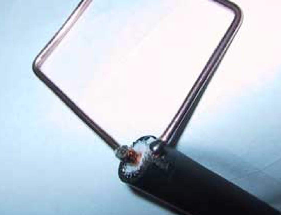
 Author evaluated a custom-built passive AM loop antenna, achieving notable DX reception including KLBJ Austin (230 miles) and WWL New Orleans (700 miles). The antenna operates solely on resonant inductive coupling, enhancing weak signal reception without external amplification. This project illustrates how fundamental RF design—calculating inductance, capacitance, and Q factor—can significantly boost performance of consumer-grade radios. Detailed construction techniques, theoretical background, and optimization strategies for effective loop antenna design are presented for amateur and experimental use.
 -
 A simple design of a 9 elem. yagi antenna for 2 meters band
 -
 Details the construction of a **multiband vertical** antenna, specifically designed for stealth operation in a rented property, covering 80m, 60m, 40m, and 30m. The author, N3OX, leverages a 12m Spiderbeam telescoping fiberglass pole as the primary support, noting its sturdiness compared to typical fishing rods while remaining light enough for quick deployment and takedown. The radiating element is a 14 gauge Flex-Weave wire, attached to the pole's top with a rubber grommet, and fed by 27 bare 18 gauge radials spread across a 40-foot square backyard. N3OX describes the impedance matching solution, opting for custom-built L-networks over a remote tuner to enable fast bandswitching. Using an MFJ-259B and EZNEC modeling, base impedances were measured and component values calculated with G4FGQ's L_TUNER and SOLNOID_3 programs. The 80m coil is wound on a 3.5-inch PVC form, while the 30m, 40m, and 60m coils are air-wound, self-supporting #10 wire. Variable capacitors are incorporated for 40m and 30m shunt elements, with the 60m impedance matched by a series inductor. The project includes a **servo-controlled** homebrew band switch, utilizing a two-pole 12-position ceramic wafer switch for remote operation, addressing the limited 80m bandwidth. The entire matching network is housed in a weather-resistant shelter constructed from lumber and aluminum flashing. N3OX reports good DX results at 100W, estimating the total cost between $150 and $250, depending on existing parts.
 -
 The page provides a project for an indoor wire antenna for the 7 MHz band, based on a design by F6CYV. It aims to help amateur radio operators lacking space to set up an antenna for 40 meters. The author shares their experience using the antenna inside an apartment, noting good reception of European signals and contacts with over 150 countries. The project details the materials and dimensions needed for the antenna, along with tips for optimal performance.
 -
 The 144-430 portable j-pole antenna is designed for amateur radio operators seeking a lightweight and efficient solution for VHF and UHF communications. This antenna is particularly useful for portable operations, allowing hams to set up quickly in various locations while maintaining excellent performance. Constructed from readily available materials, it can be easily homebrewed, making it an ideal project for both beginners and experienced operators alike. The j-pole design offers a simple yet effective configuration that provides a good match across the 144 MHz and 430 MHz bands. Its vertical polarization and omnidirectional radiation pattern make it suitable for local communications and simplex operations. This antenna can be deployed in various environments, whether in the field or at home, and is well-suited for mobile applications. With proper construction techniques, operators can achieve optimal performance, enhancing their ability to make contacts during contests or casual QSOs.
 -
 Great first time J-pole project. Covers most of the basics. This small and thin design also makes it good for several stealth applications.
 -
 For radio amateurs considering homebrew antenna projects, this resource details several designs from WE6W, an experienced operator. It covers the construction and characteristics of a _160 Meter QRP Loop Antenna_ optimized for high voltage, along with standard and folded variations of the double bazooka antenna. The site also presents a unique Field Day antenna design and instructions for building a Sterba Curtain, a directional array known for its gain. Each design includes practical insights from the author's building experience. The author provides comparative data, such as the performance of a standard bazooka against a traditional dipole, offering real-world context for antenna selection. The Sterba Curtain section includes notes on its beamwidth and gain, crucial parameters for directional operation. These designs are suitable for hams looking to experiment with cost-effective, high-performance antennas for various bands and operating scenarios, from QRP on 160m to directional DXing with a Sterba Curtain, which can offer significant forward gain, often exceeding **10 dB**.
 -
 The Cubic Quad antenna is a commonly homemade antenna in the range of about 150 odd MHz. Our little project was to design one of these for use in the 2.4GHz range for 802.11 wireless LANs.
 -

-
 The boomless quad antenna is a unique design that offers versatility for amateur radio operators. This antenna consists of two half-wave dipoles arranged in a square or circular shape, allowing for both vertical and horizontal polarization depending on the feed point. The design facilitates easy installation and rotation, making it suitable for various operating conditions. The construction utilizes strong materials, such as bamboo, and incorporates waterproofing techniques to enhance durability. This project outlines the necessary dimensions and materials, including copper wire and insulators, to successfully build the antenna. It emphasizes the importance of tuning each radiator element for optimal performance. The boomless quad is particularly effective across multiple HF bands, including 14 MHz, 21 MHz, and 28 MHz. By following the detailed instructions, operators can achieve a reliable and efficient antenna setup that enhances their DXing and contesting capabilities.
 -
 The RXO Unitenna, a vertical wideband antenna, offers operation across the 7-21 MHz spectrum, covering the 40, 30, 20, 17, and 15-meter amateur bands. This design focuses on achieving a low SWR across a broad frequency range, making it suitable for general HF operation without requiring an external antenna tuner for minor SWR variations. The antenna utilizes a unique loading coil and matching network to maintain efficient radiation characteristics across its operational bandwidth. Construction details within the PDF document include specific dimensions for the radiating element and the counterpoise system, which is critical for vertical antenna performance. The design incorporates readily available materials, simplifying the build process for radio amateurs. Performance graphs illustrate the SWR characteristics across the 7 MHz to 21 MHz range, demonstrating the antenna's wideband capabilities. The document also provides guidance on feedline connection and grounding considerations for optimal field deployment. This vertical antenna configuration is particularly useful for hams with limited space, offering a compact footprint compared to horizontal wire antennas.
 -
 Optimizing the impedance transformation and common-mode current suppression in antenna systems often involves selecting an appropriate balun. This project presents a **hybrid balun** design, combining characteristics of both voltage and current baluns to achieve superior performance, particularly when used with an antenna tuner. The design addresses issues like **common-mode current** on the feedline, which can distort the antenna's radiation pattern and introduce RFI in the shack. The construction details include winding techniques for the toroid core, component selection, and practical considerations for integration into an existing antenna system. Performance comparisons are drawn against conventional balun types, highlighting the hybrid balun's effectiveness across the HF bands. The resource provides insights into the current distribution and impedance matching properties, crucial for efficient power transfer and reduced SWR.
 -
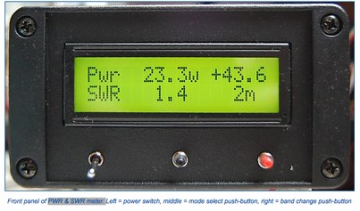
 The project details a DIY SWR/Wattmeter designed around an _Arduino Uno_ shield, providing capabilities to measure RF power from 2 to **200 watts** and Standing Wave Ratio (SWR) for HF amateur radio bands. This construction features a compact design, integrating the measurement circuitry directly onto a custom PCB that interfaces with the Arduino Uno microcontroller. Key components include a directional coupler for sensing forward and reflected power, precision rectifiers, and analog-to-digital conversion for processing RF signals. The Arduino firmware handles calibration, calculations, and displays the results on an integrated LCD, offering real-time feedback on antenna system performance. The design prioritizes simplicity for homebrewers. Performance specifications indicate accurate readings within the **2-200W** power range, suitable for typical QRP to medium-power HF operations. The project provides schematics and a basic overview of the software logic.
 -
 Two well performing 50 MHz antennas designed with W7EL EZNEC along to many other antenna projects and related articles
 -
 This Vertical antenna design by David Reid for lower bands focuses on achieving effective DX communication by optimizing the antenna low-angle radiation for long-distance contacts. The design incorporates techniques like linear loading and capacity hats to reduce the antenna's height while maintaining performance, especially on 40m and 80m bands. Building a solid ground plane and using quality materials ensure efficiency and durability. Although vertical antennas can be complex to build, this project simplifies the process, making it accessible for ham operators seeking strong, reliable signals.
 -
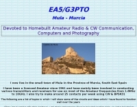 Presents a collection of homebrew amateur radio projects and circuit ideas developed by EA5/G3PTO, a licensed operator since 1961. The resource details various transmitters and receivers constructed for frequencies ranging from 1.8 MHz to 10 GHz, emphasizing CW and BPSK31 operation. Specific projects covered include a "Bombproof 7Mhz Receiver" and several keying circuits, providing insights into designs that have proven effective over decades of use. The site also integrates personal photography, showcasing scenes from the West of England and Southeast Spain, reflecting the author's interest in connecting with other amateurs and visualizing their locations. Additionally, it offers a curated list of links to other home construction sites and DX information, serving as a hub for DIY enthusiasts and DXers. The content is distinctively personal, blending technical project documentation with a broader view of the amateur radio lifestyle and community engagement.
 -
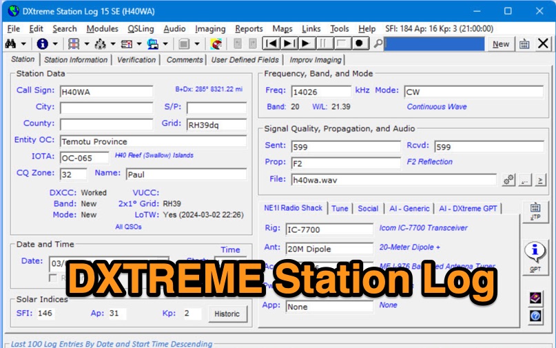 DXtreme Station Log 15 SE provides comprehensive logging functionalities for Amateur Radio operators, featuring robust _Logbook of the World_ (LoTW) support for automatic uploads, QSO record status capture, and QSL processing. The software integrates with _Afreet Omni-Rig_ for rig control and offers worked-before notifications for _WSJT-X_ and JTDX, streamlining digital mode operations. Its DX Spot Checker queries servers to indicate DXCC/VUCC status based on the user's database, utilizing Rich Site Feed or Grid Feed options. Key features include Improv Imaging and QSL Imaging for managing screenshots, documents, and QSLs, alongside Performance Reports for tracking station activity. The application incorporates AI functionalities, such as a Generic AI feature and a dedicated DXtreme GPT for specific instructions. DXtreme Interchange facilitates digitizing paper logbooks into ADIF-based project files, enabling rapid data entry and automatic field population. DXtreme Monitor Log 14, designed for radio monitoring, logs stations across the spectrum, including a Schedule Checker for broadcast stations from Aoki, EiBi, and FCC AM sites. It integrates with Afreet Band Master to identify needed Amateur Radio entities and supports reception report creation for QSLs.
 -
 A self-supporting vertical antenna design for stationary-mobile HF-VHF operation is presented, emphasizing ease of construction with common materials like a fiberglass fishing rod and PVC pipe. The design focuses on creating a set of no-tuner monoband radiators for bands such as **2m**, **6m**, 10m, and 12m, with an overall radiator support length of 3.3m. The construction process details the assembly of the antenna base using a magnetic mount, PL-259 connector, and PVC pipe sections, which then supports the telescopic fishing rod. Radiator extensions are cut to achieve quarter-wave resonance on specific bands, with detailed instructions for 6m (50-51 MHz), 10m (28.5 MHz), and 12m (24.9 MHz). For lower HF bands like 15m, 17m, and 20m, the design incorporates base-loading coils, with specific turn counts provided (e.g., 21 turns for 20m). The project also suggests using an _antenna analyzer_ for precise tuning of extensions and coils, moving beyond theoretical values to achieve optimal performance. The author, _IK1ZYW_, notes that for 80m and 160m, the antenna becomes less efficient as a vertical, suggesting alternative configurations like an inverted-V dipole or asymmetrical inverted-L.
 -
 The Flower Pot Antenna project details a portable dual-band antenna primarily operating on 10 meters, with secondary resonance near the 30-meter band. Construction involves winding RG58 coaxial cable uniformly around a large plastic flower pot, approximately 70cm high with a 60cm top diameter. The design eliminates the need for radials, contributing to its compact and lightweight nature. Key construction steps include soldering the inner conductor to the shield at one end of the wound cable and connecting the wound cable's shield to the rig cable's inner conductor at the base. An LC network, comprising a variable capacitor (0-200pF) and an inductor (10 coils, 5cm diameter, 2mm wire), is inserted between the wound cable's inner conductor and the rig cable's shield. Tuning is performed with an antenna analyzer, adjusting cable length and the variable capacitor for optimal impedance on 10 meters. The antenna performs effectively when installed horizontally.
 -
 This sketch will read RF power and SWR from any SWR bridge, designed to work on VHF UHF bands
 -
 This is a project to develop an Open Source reference design for a 1500 watt solid state linear amplifier for 10 through 160 meters by K6IF
 -
 The project details modifications to an ARK-40 QRP CW transceiver kit, specifically replacing its original thumbwheel frequency selectors with a **BASIC STAMP BS-II microcontroller** and an optical shaft encoder. The redesigned control circuitry outputs a BCD code to the ARK-40's synthesizer, enabling more convenient knob-type tuning. This modification significantly alters the user interface, moving from discrete frequency selection to continuous tuning. Operating frequency is presented on an LCD readout, offering two distinct display modes: a "bandspread dial" mode that simulates an analog dial scrolling across the display in 1 kHz increments, and a conventional digital readout with 100 Hz resolution. Pushing the main tuning knob toggles between these modes, providing both rapid band traversal and fine-tuning capabilities. The software for the BASIC Stamp is written in P-Basic, addressing the challenge of accurate analog dial simulation. Physical modifications include fabricating a custom PC Board for the STAMP, mounting it with an L-bracket to the optical encoder, and creating a new front panel. The front-mounted speaker was relocated to accommodate the new tuning knob and display, transforming the **ARK-40 transceiver** into a more user-friendly rig with its built-in CW keyer and 5 watts of power.
 -
 The directory lists several files, including `_template1.html` and `_template2.html`, last modified in 2006 and 2004 respectively, indicating a historical web project. Key scripts like `hfcc_cfm.pl` and `index.cgi`, updated in 2011, suggest a **CGI-based application** for searching shortwave broadcast schedules. The presence of `_template1.tpl` and `_template2.tpl`, both modified in 2015, points to a templating system for dynamic content generation. The file `hfcc_create-fill_mys..>` (likely `hfcc_create-fill_mysql.pl`) implies interaction with a database, possibly MySQL, for storing and retrieving **HFCC (High Frequency Co-ordination Conference)** schedule data. The `lang.cgi` script, last updated in 2002, suggests early support for multilingual interfaces or language-specific content delivery. The `q.txt` file, a small 804-byte text file, could be a query log or a simple data file. The overall structure indicates a system designed to process and present shortwave broadcast information, likely by querying a database of scheduled transmissions on various HF frequencies. The file modification dates suggest the project was actively developed and maintained over a period spanning more than a decade, with core components last updated around 2011 and templates in 2015.
 -
 A 144 MHz kilowatt amplifier project details the construction and performance of a high-power VHF linear using the GU74b tetrode. This Russian tube, equivalent to the Svetlana 4CX800, is noted for its conservative datasheet ratings, performing closer to 800-1000W anode dissipation in practical applications. The design prioritizes compactness and achieves 1.2 kW output with only 20W of drive power, demonstrating a 70% efficiency at 2.5 kV plate voltage. The amplifier has been successfully deployed in demanding _EME_ (Earth-Moon-Earth) operations since June 1994. Challenges encountered during development included achieving stability with a grid-1 input configuration. The author, _CT1DMK_, opted not to publish the full design due to its complexity, suggesting it might be difficult for less experienced builders to replicate successfully. However, he invites direct contact for those with specific interest in the design. Future plans include a "144MHz GS35b compact amplifier" project, promising another kilowatt-plus design. This resource offers insights into high-power VHF amplifier construction and the practical application of specific power tubes.
 -
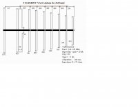
 This project details three variants of a vertical half-wave antenna design for the 4-meter (70MHz) amateur radio band. The antennas use end-feeding with a parallel-tuned circuit for impedance matching to 50-ohm coaxial cable. The first variant uses suspended flexible wire for portable use, the second employs a fiberglass rod with internal wire for permanent outdoor installation, and the third utilizes aluminum tent poles for quick mobile deployment. Despite the narrow bandwidth of the matching circuit, this suits the narrow 4m FM allocation well. The design offers an effective omnidirectional radiation pattern and can be constructed with readily available materials.
 -
 The SoftRock-40 is a small, low-cost, good-performing "software defined radio" receiver that plugs into a computer USB port and delivers I-Q audio signals to the computer's sound card. It was designed by Tony Parks, KB9YIG and Bill Tracey, KD5TFD as an "SDR sampler project" for hams everywhere to easily try out software defined radio.
 -
 The page provides a detailed guide on building a successful 160 Meter short TX loop antenna, with specific dimensions and tuning instructions. It includes information on the design, construction, and tuning of the antenna, as well as the materials required. The intended audience is amateur radio operators looking to build an effective antenna for the 160 Meter band.
 -
 Catalogs a diverse array of Software Defined Radio (SDR) projects and realizations, systematically classified by their sampling methodologies and underlying hardware architectures. The resource delineates projects into categories such as those utilizing soundcard sampling of traditional transceiver audio outputs (Type Ia), mono soundcard sampling of intermediate frequencies (Type R1x-x-xx), stereo soundcard sampling of I/Q IFs (Type Q1x-x-xx), dedicated stereo audio ADC sampling of I/Q IFs (Type Q2x-x-xx), direct antenna RF signal sampling with off-the-shelf acquisition boards (Type R3x-x-xx), dedicated RF ADC sampling of analog IFs (Type R2x-x-xx), dedicated RF ADC sampling of direct antenna RF signals with ASIC-based processing (Type R4x-A-xx), FPGA-based processing (Type R4x-F-xx), and specialized IF chipsets combining ADC and DDC functions (Type Dxx-S-xx). Each entry provides a brief description, often including pricing, availability of source code, and specific hardware components like ADCs, DACs, DDS, and FPGAs. The compilation presents various practical applications, from PSK31 and Packet radio implementations to adaptations of the DRM standard for amateur radio bandwidths, such as Hamdream and WinDRM. It features specific hardware designs like the SoftRock-40 for the 40-meter band, the Firefly SDR for 30m and 40m, and more complex systems like the Quicksilver QS1R, which employs a 16-bit 130 Msamples/s ADC and an Altera Cyclone III FPGA. The resource also lists sample processing software, RF front-end designs, and academic/commercial SDR initiatives, offering insights into different approaches for I/Q conversion and digital signal processing in SDR systems.
 -
 The Inverted L antenna is a versatile and efficient design suitable for small gardens, allowing amateur radio operators to operate on multiple bands. This project outlines the construction of a 5-band inverted L antenna, which can cover HF bands effectively. The design is particularly advantageous for those with limited space, as it requires minimal ground space while providing good performance. The antenna can be easily constructed using common materials, making it accessible for both beginners and experienced hams. In this guide, GM0ONX shares detailed instructions on how to build the inverted L antenna, including dimensions and tuning tips. The project emphasizes the importance of proper installation and grounding to ensure optimal performance. Additionally, it discusses the antenna's compatibility with various transceivers and the potential for portable operation. This resource is ideal for hams looking to enhance their station with a multiband antenna that performs well in limited space.
 -
 One common challenge in antenna systems is mitigating common-mode current on the feedline, which can distort radiation patterns and introduce RF in the shack. This project details a 1:1 balun design that ingeniously avoids traditional ferrite beads, often a costly component, by substituting them with steel wool. The steel wool, when integrated into the balun's construction, effectively attenuates unwanted RF on the outer braid of the coaxial cable, ensuring that the antenna radiates efficiently and as intended. The construction involves winding coaxial cable through a PVC former, with the steel wool strategically placed to provide the necessary common-mode impedance. This method offers a practical and economical alternative for hams looking to build effective baluns without the expense or availability issues associated with ferrite cores. The design principles focus on creating a balanced feed to the antenna, crucial for optimal performance of dipoles and other balanced radiators. Experimentation with such designs can lead to improved field results, particularly for those operating with limited budgets or seeking innovative solutions for their antenna systems. The simplicity of using readily available materials like steel wool makes this a compelling build for many radio amateurs.
 -
 Over 45 years of amateur radio experience inform the homebrew projects detailed on this personal website, with a particular focus on microwave frequencies. The site showcases a 24 GHz transverter and a more recent 47 GHz transverter, demonstrating practical construction techniques for extreme high-frequency operation. These projects often involve custom circuit design and careful component selection to achieve stable performance at millimeter-wave bands. Key projects include a _harmonic converter_ for frequency measurement and a tracking spectrum analyzer, essential tools for microwave experimenters. The site also documents a CW sidetone generator and a TX/RX sequencer, illustrating fundamental building blocks for radio equipment. Details on a digital frequency meter and an S-meter/dBm meter provide insights into test equipment construction. Specific achievements, such as a **24 GHz** tropo QSO with DK3SE in 2021, highlight the operational success of these homebrewed systems. The content reflects a long-standing dedication to self-sufficiency in amateur radio, providing practical examples for those interested in building their own gear.
 -
 Constructing a **2-meter** J-pole antenna from readily available copper plumbing components offers a robust and cost-effective solution for VHF operation. This design, dubbed the "Plumber's Delight," functions essentially as a half-wave dipole fed by 50-ohm coax via a **gamma match**. It incorporates a quarter-wave copper tubing support, which, when affixed to a metal mast or tower, enhances forward power in the direction of the radiating elements. The original configuration utilized a small ceramic trimmer capacitor for the gamma match, suitable for up to 10 watts. A subsequent modification replaced this with a 50 pF variable capacitor housed in a plastic enclosure, accommodating higher RF power and improving weather resistance. The antenna elements are secured using a copper "T" fitting, and an SO-239 connector mounts directly to this fitting. Performance includes gain away from the support mast, and tuning is straightforward by adjusting the gamma match capacitor for a 1:1 SWR. The total cost for materials, excluding the capacitor and coax, can be under $10.
 -
 CAT control and logging software project especially developed for the YAESU FT-100 transceiver. The program is based on the design of FT847-SuperControl.
 -
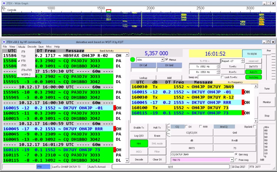 JTDX is an open-source software application for amateur radio weak-signal digital communication. It supports digital modes including FT8 and JT9. The software operates on _Windows_, _Linux_, and _macOS_ platforms. JTDX is designed for improved decoding of weak signals, a function also performed by WSJT-X and MSHV. The software facilitates weak signal decoding and transmission. It integrates with logging systems for QSO management and can automate tasks such as call management and remote RTX control. JTDX is utilized in contexts such as DXing and contests. DXZone Focus: FT8 | JT9 | Weak Signal | Multi-platform
 -
 Unified Microsystems presents a range of amateur radio products, notably the **XT-4 MK2 CW Memory Keyer**, a battery-powered iambic keyer designed for portable operations like Field Day, POTA, SOTA, and DXpeditions. It features four non-volatile memories, each storing approximately 240 Morse characters, and operates at speeds from 8-45 WPM. The XT-4 MK2 also includes an auto power save function and paddle reverse, making it adaptable for multi-operator setups. Beyond the XT-4 MK2, the site details the **W9XT Contest Card**, a PC plug-in board offering DVK and CW interface capabilities, allowing operators to record and playback CQs and contest exchanges. Other offerings include the BevFlex-4X RX Antenna System, RAS-4 RX Antenna Switch, VK-64 Voice CW Keyer, and various USB interfaces. Additional products cover electronic development, such as the ATS-1 Terminal Shield for Arduino™ and VR-X Power Supply Voltage Regulators, demonstrating a broader scope beyond just operating accessories. The XT-4Beacon MK2 / CW IDer is also highlighted for beacon projects, capable of storing messages up to 5 minutes at 25 WPM.
 -
 CuteSDR Open-Source application for MacOSX , Linux, and Windows designed to run with RFSPace SDR receiver
 -
 A 2-meter Turnstile antenna, detailed for amateur satellite communication, offers a straightforward build for those looking to engage with orbiting transponders. The author, WB8ERJ, shares his personal design and construction methods, emphasizing the antenna's simplicity and effectiveness for LEO (Low Earth Orbit) satellite work. This design provides a circularly polarized signal, crucial for mitigating _Faraday rotation_ and signal fading often encountered with linearly polarized antennas when tracking satellites. Construction involves readily available materials like PVC pipe and copper wire, making it an accessible project for many hams. The article includes practical advice on element spacing and feed point considerations, drawing from the author's hands-on experience in the shack and field. It highlights the antenna's utility for receiving signals from various amateur satellites, including the popular AO-91 and AO-92. The Turnstile's inherent omnidirectional pattern in the horizontal plane, combined with its circular polarization, yields consistent signal reception, often resulting in **stronger decodes** and **more reliable contacts** compared to basic dipoles or verticals.
 -
 Constructing a high-power solid-state amplifier for HF operations presents unique challenges, particularly when aiming for significant output like 600 watts. This project details an amplifier design employing **Motorola MRF150** FETs, a common choice for their robust performance in RF power applications. The design emphasizes achieving substantial power output, a critical factor for effective DXing and contesting, where every decibel can make a difference in signal propagation and readability. While specific circuit diagrams or construction details are not directly presented on the current page, the mention of MRF150 FETs points towards a design that would typically involve push-pull configurations, impedance matching networks, and robust power supply considerations to handle the high current demands. Such amplifiers are often built with an eye towards linearity and efficiency across the HF bands. Amateurs pursuing similar high-power solid-state projects often share insights on thermal management, intermodulation distortion, and component sourcing, all vital for a stable and reliable amplifier capable of delivering 600 watts into a proper antenna system.
 -
 The homemade CW paddle key design, inspired by a QRP homepage, utilizes soldered PC board material for its construction. The builder, DL5NEJ, modified an existing design to achieve a smaller footprint, preferring a compact setup for portable operations. This paddle was specifically built to complement a Wilderness Radio SST20 QRP transceiver kit, demonstrating its suitability for low-power operations. The project details suggest a straightforward assembly process, with the primary components being readily available PC board scraps. The design emphasizes simplicity and functionality, aiming to provide a reliable keying experience comparable to commercial paddles like the Bencher. Performance evaluations indicated the simple paddle operates effectively, prompting further exploration into similarly minimalist QRP rig designs. Additional construction details for a similar paddle are available from PA0CMU.
 -
 A 40-meter reversible _Moxon rectangle_ antenna project details its construction and performance, featuring 51-foot long sides and 7.7-foot turned-in sections. The design incorporates a 16.5-foot boom, with elements spaced 1.1 feet apart, constructed from #14 covered wire. It utilizes two double-pole relays for switching between NE and SW directions, achieving F/B ratios up to 40 dB on CW and 30 dB on SSB, with distinct reflector stub settings for each mode. This antenna replaced a full-size 2-element Yagi, demonstrating comparable forward gain while offering superior F/B ratios and directional flexibility. _EZNEC_ modeling indicates only 0.2 dB less forward gain than the Yagi. The system uses no baluns, relying on half-wave feedlines and switched stubs for impedance matching. The antenna is tree-supported at 45 feet, with its effective radiation height modeled at 80 feet due to local terrain, enhancing its performance over a nearby lake.
 -
 Details a practical QRP wattmeter construction, leveraging a simplified SWR meter design by JA6HIC. The project focuses on a forward-only power measurement circuit, providing a functional instrument for RF power levels from milliwatts up to 5 watts. It maintains a 50-ohm input and output impedance, suitable for typical QRP transceivers and antenna systems. The resource includes the schematic for the "VSW" (Very Simple Wattmeter) and outlines a six-step alignment procedure. This calibration process involves using a known RF source up to 5W, setting full-scale deflection, and marking power increments. It also addresses minimizing frequency effects on readings with a 100pF trimmer capacitor, noting that measurement error is highest at the lower end of the scale. Construction notes mention using a piece of RG-213 coaxial cable for the inductance and coupler, with the wattmeter assembled in early 2003. The author provides an example measurement showing 0.8W into a dummy load and 1W into a 3-element beam.
 -
 Great first time J-pole project. Covers most of the basics. This small and thin design also makes it good for several stealth applications.
 -
 PA3FWM's software defined radio (SDR) page documents his extensive hardware and software development efforts between 2004 and 2009. Initial experiments utilized a direct conversion receiver with 90-degree phase difference, feeding a PC soundcard at 48 kHz sample rate, covering 24 kHz of spectrum around a 7080.5 kHz local oscillator. This setup, similar to AC50G's QEX 2002 article, allowed for basic I/Q signal processing to distinguish signals above and below the LO frequency. Limitations included fixed crystal frequencies, 16-bit dynamic range, and narrow bandwidth. Subsequent hardware iterations aimed for enhanced performance, incorporating external 24-bit ADCs with 192 kHz sample rates, connected via 10 Mbit/s Ethernet. A **MC145170-based PLL** and programmable octave divider provided a 58 kHz to 30 MHz tuning range. The **Tayloe mixer** was employed, with differential outputs feeding a PCM1804 ADC. An ATmega32 microcontroller handled serial data conversion to Ethernet frames, though without CRC calculation due to processing constraints. Later designs integrated AD7760 2.5 Msamples/second ADCs and a Xilinx Spartan-3 FPGA, enabling direct reception of 0-1 MHz spectrum and eventually 2.5 MHz bandwidth across the shortwave spectrum. Software was refactored to use an initial 8192 non-windowed FFT for efficient high-bandwidth processing. The project culminated in a two-way QSO on 21 MHz using the developed hardware and software, demonstrating transmit capabilities with a D/A converter. The system exhibited a 2.5 MHz wide spectrum display and a zoomed 19 kHz display, capturing signals like ionospheric chirp sounders and RTTY contest activity. Challenges included noise leakage from digital circuitry and cooling for high-power dissipation components.
 -
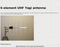 A standard 6 elements design scaled for UHF application. All material used in this project are easily obtainable tubes and rods which is limited within a total budget of $18.
 -
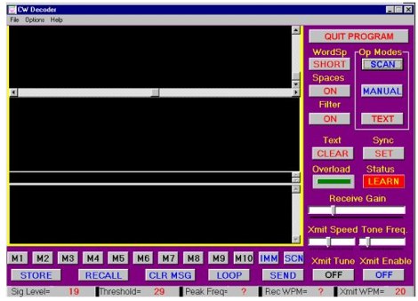 The CW Decoder program facilitates copying Morse code with a computer, displaying decoded CW as text, and generating a sidetone. It incorporates a spectrum display of the audio, allowing operators to select a specific audio frequency for decoding via a sliding cursor. This utility also enables keyboard-based transmitter keying, supporting full CW break-in operation for efficient QSO management. Developed by WD6CNF, the software is a Windows-compatible application designed to assist amateur radio operators in their CW activities. Its features cater to both decoding received signals and transmitting via keyboard input, streamlining the CW operating experience. Functionality includes real-time audio analysis and signal processing, providing a visual representation of the CW signal. The program's integrated keying capability offers a direct interface for transmitting, enhancing its utility as a comprehensive CW station tool.
 -
 Several projects which will allow you to build your own RF design test equipment.
 -
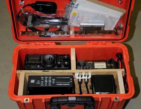 The best way to describe a go-box is a complete amateur radio station in a box. An example is described in this article. The project describes building a portable amateur (ham) radio station, known as a "go-box," housed in a durable orange Pelican case. The go-box contains all necessary radio equipment except for external power and antennae, which are carried separately. It includes items like a Yaesu transceiver, power supply, antenna tuner, speaker, and a clock. The case is designed for mobility and visibility, with a vertical layout to allow in-vehicle operation. Future upgrades might include cooling fans, an LED lamp, and built-in antennae for better functionality in various conditions.