Search results
Query: frequency
Links: 713 | Categories: 31
Categories
- Ham Radio > Band Plans > Frequency coordination
- Manufacturers > Test Equipment > Frequency Counter
- Technical Reference > Frequency Counter
- Software > Low Frequency
- Technical Reference > Radio Frequency Interference
- Manufacturers > Antenna Analyzers
- Technical Reference > Calculators
- Software > Databases
- Technical Reference > DTMF
- Technical Reference > Duplexers
- Radio Equipment > HF Transceivers > Elecraft K3
- Manufacturers > Antennas > VHF UHF Microwave > Ground Plane Antennas
- Operating Modes > HF Operations
- Propagation > MUF Indicators
- Radio Scanning > Nature
- Technical Reference > Radio Frequency Interference > Noise Reduction
- Radio Scanning > Police Scanning
- Radio Scanning
- Radio Scanning > Radio Scanning Reference
- Operating Aids > Radio Spectrum
- Radio Scanning > RailRoad
- Ham Radio > Resources
- Technical Reference > RF Design
- Manufacturers > Antennas > VHF UHF Microwave > Satellite antennas
- Manufacturers > Test Equipment > Spectrum Analyzers
- Operating Modes > SSTV
- Propagation > Sunspots
- Shortwave Radio > SWL Resources
- Shortwave Radio > Broadcasters > Time Signal Radios
- Manufacturers > Software Defined Radio > Upconverters
-
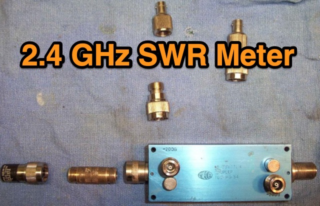 This is a simple 2.4 GHz SWR meter which is based around surplus microwave hardware which can be easily found. The main component is a MECA -20/-20 dB Directional Coupler which has a frequency range of approximately 700 MHz to 2.5 GHz.
 -
 The morsecodeworld.org web application provides an online Morse code decoder and encoder, facilitating real-time conversion between text and International Morse code. It supports adjustable transmission speed (Words Per Minute), sidetone frequency pitch (Hz), and output volume, allowing users to customize their learning and practice environment. The tool includes a quick reference chart for the Morse alphabet and focuses exclusively on International Morse, aligning with contemporary amateur radio licensing and on-air practices, distinguishing it from historical American Morse code. This web-based utility enables users to type text for encoding into Morse audio or paste Morse code for decoding into plain text, offering immediate feedback on timing and character spacing. It supports both visual and auditory learning by providing adjustable parameters for speed and tone. The platform is designed for self-assessment, encouraging users to practice copying and sending, and to identify and correct common errors in character recognition and timing.
 -
 This air-core solenoid style RF inductor calculator calculates the inductance, wire size, number of turns, and other parameters for an air-core solenoid inductor used in radio frequency (RF) circuits, based on user input of frequency, desired inductance value, and physical dimensions.
 -
 This page presents an online calculator tool for determining the dimensions of various HF wire antennas operating between 1.8-30 MHz. Users input their desired resonant frequency to obtain precise measurements for four popular antenna types: standard flat-top dipole, inverted Vee, quad loop, and equilateral delta loop. The calculator provides comprehensive measurements including leg lengths, minimum heights, horizontal spreads, and feedpoint distances. Accompanying the calculator are detailed technical explanations, construction notes, and installation guidelines for each antenna type, making it a practical resource for amateur radio operators building their own antennas.
 -
 Explains the fundamental purpose of a repeater, detailing how these automated relay stations overcome distance and terrain limitations for VHF/UHF communications. It traces the historical development from early Bell Telephone Labs "relay" stations in 1922 to Art Gentry, W6MEP's, pioneering K6MYK amateur radio repeater in the mid-1950s, which remains active today. The resource clarifies the distinction between simplex and duplex operation, including the unique function of a "parrot repeater" for single-frequency recording and playback. Delving into the internal workings, the guide breaks down a repeater into its core components: the antenna system, feedline (often _Heliax_ or hardline for minimal loss), duplexer, receiver, transmitter, and controller. It emphasizes the critical role of the duplexer in preventing receiver desensitization by isolating transmit and receive signals, even with distinct frequencies. The discussion highlights the importance of high-performance, durable antennas and low-loss feedlines, citing examples of equipment installed in the 1960s and 1970s that are still in perfect working order. Operating a repeater is also covered, with an explanation of frequency offset (e.g., the 600 kHz standard for 2 meters) and the function of _CTCSS_ (PL tone) for access. It outlines standard input/output offsets for various bands, from 6 meters to 23 centimeters, while noting regional variations. The guide also touches on features like autopatch and Digital Voice Recorders (DVRs), providing a solid foundation for understanding repeater technology and usage.
 -
 Operating within the low-frequency spectrum, transformers serve critical roles in antenna systems, particularly for 160m applications. The resource details the construction and performance of 1:1 transformers built on BN-73-202 cores, emphasizing their use as hybrid combiners or phase inverters for RX antenna arrays. Measurements reveal that these transformers exhibit minimal losses, around 0.12 dB at 1.8 MHz, with variations based on wire type and number of turns. The analysis includes comparative data on transformer performance, highlighting the impact of different winding techniques on frequency response. Notably, the use of coaxial cable for winding improves bandwidth while maintaining low-frequency efficiency. The resource also discusses braid breaker transformers, which minimize inter-winding capacitance, achieving low losses around 0.21 dB at 1.8 MHz. These insights are crucial for optimizing low-band antenna systems, allowing operators to make informed decisions regarding transformer design and implementation.
 -
 WSJTX-Controller-v2, or Otto, functions as an assistant for the WSJT-X amateur radio program, specifically designed to enhance operational efficiency for weak signal digital modes. The software automates several key tasks, including call management, prioritizing DX stations based on user-defined criteria, and optimizing frequency selection within the WSJT-X interface. It requires a modified version of WSJT-X to function correctly, integrating directly with its core processes to provide augmented control. Otto supports various digital modes, facilitating auto-logging of contacts and generating specific alerts for desired stations or conditions. It is engineered to streamline the workflow for operators engaged in DXing and general weak signal communication, offering features like automatic CQ responses and intelligent band monitoring. The utility is not compatible with certain other amateur radio software and is explicitly noted as unsuitable for contest operations or the WSJT-X Hound mode, indicating its specialized focus on non-contest DX and casual operating. The project's GitHub repository provides the source code and documentation, allowing users to review its implementation and contribute to its development. The software's design emphasizes automation to reduce operator intervention during routine digital mode operations.
 -
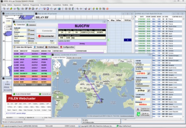 DXFile is a Windows shareware application designed for amateur radio operators, providing comprehensive log management capabilities. The software, developed in Pascal, facilitates real-time and deferred QSO entry, automatically populating fields like frequency, mode, and DXCC country based on user input and system time. It includes features for searching, modifying, and deleting QSO records, with options to sort logs by date, callsign, or entry order. The program offers various printing functions, including QSL card labels in multiple formats, and can generate standard logbook printouts. Beyond basic logging, DXFile integrates modules for tracking progress towards major operating awards such as DXCC, _IOTA_, WAZ, WAS, DDFM, and DIFM. It provides detailed summaries of contacts by band and mode, including graphical representations of HF traffic. A dedicated QSL Manager module assists in processing received QSLs, allowing users to mark confirmations and print multi-line QSL labels. The application also incorporates a DXCC list viewer, which can be updated to ensure accurate country and zone data for logging and award tracking. A distinctive feature is its HF propagation prediction module, which calculates optimal frequencies and signal levels for paths between **250 km** and **6000 km**, considering both E and F layer ionospheric conditions. This module helps operators determine the best times for long-distance contacts. Additionally, DXFile includes a _Web-Cluster_ interface, enabling connection to various DX cluster servers like DXLITE, DXSCAPE, and NC7J for real-time spot information.
 -
 The antenna I built was inspired by a portable delta loop designed by Doug DeMaw, W1FB. Given that I constrained myself to a 50-foot roll of speak wire, I scaled my antenna for the 20M band. Using the formula, 1005 divided by the frequency in megahertz, I calculated a total length of 71 feet (21.6 meters) for the center of the 20M band.
 -
 The document discusses the classifications of sunspots and their potential for solar flare activity, categorizing them into Alpha, Beta, and Delta groups based on their magnetic field characteristics. It explains how these classifications relate to the likelihood of solar flares, ranging from minor to extreme events. The report also outlines the geomagnetic indices and conditions that affect high-frequency (HF) radio propagation, emphasizing the effects of solar flares on radio communication and geomagnetic storms. The information is geared towards amateur radio operators, providing insights into how solar activity influences HF radio operations.
 -
 This project revisits a minimalist software-defined radio (SDR) receiver built using a Raspberry Pi Pico, now optimized for simplicity and affordability. Designed for breadboard assembly with through-hole components, the receiver covers 0–30MHz, supporting CW, SSB, AM, and FM modes with an OLED display and spectrum scope. Key improvements include enhanced frequency accuracy, reduced op-amp saturation, and lower-cost components. Powered by three AAA batteries, it delivers standalone operation for global signal reception. Ideal for hobbyists, the design fosters experimentation and is documented with firmware and schematics available online.
 -
 The HB9CV antenna calculator aids amateur radio enthusiasts in designing antennas for VHF and UHF bands. By inputting the working frequency, users can obtain crucial dimensions like dipole lengths and distances. The tool, based on the HFSS antenna model, provides data on impedance, VSWR, and gain, optimizing front/back radiation ratios. It includes tips for fine-tuning using a Г-matching balun and compensating capacitor, ensuring effective performance and minimal VSWR for enhanced radio communications and direction finding.
 -
 Learn how to design and analyze a folded trifilar antenna for the 80-meter band. Based on a description from RAF antennas between 1940 and 1970, this article provides step-by-step guidance on modeling the antenna, calculating resonance frequency, adjusting dimensions, and verifying performance. Perfect for hams looking to improve their antenna setup for better transmission and reception on the 80M band.
 -
 This document details the construction, programming, and operation of a modular WSPR transmitter. The transmitter utilizes an ESP8266 NodeMCU, an SI5351 synthesizer with a TCXO for stability, and selectable low pass filters. Construction involves soldering headers, components, and assembling filter module. The ESP8266 is programmed via the Arduino IDE, requiring library installations and code modifications, including network credentials, callsign, and frequency . The transmitter is powered by USB or Vin terminals and its frequency is selected by jumpers and software settings. The document also covers FCC restrictions and how to use the WSPR network
 -
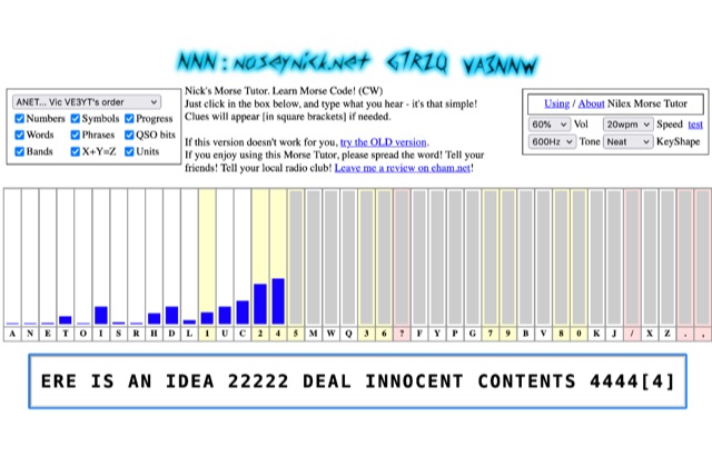 The **Nilex Morse Tutor** is an HTML5 web application designed to teach Morse code reception, adapting to user proficiency by adding new characters as readiness is detected. It prioritizes practice on less familiar letters, numbers, symbols, words, and phrases, while minimizing repetition of already mastered elements. The program offers multiple learning orders, including "Q7ZG..." (Ward/Jim's), "KMRS..." (PU5EPX/Koch), "KMUR..." (lcwo.net), "AENT..." (CWops CW Academy), "TEAN..." (Stephen C Phillips), "ANET..." (Vic VE3YT), and "ETI5..." (Ham Whisperer), alongside an alphabetical option. Users can customize the learning experience by enabling or disabling automatic progression, and selecting specific content categories such as numbers, symbols, words, phrases, QSO bits, Ham Radio Bands, X+Y=Z math, and units. Audio settings are adjustable for volume, speed (WPM), tone frequency, and keyshape/keying envelope, allowing for a personalized auditory environment. The interface provides visual feedback with blue bars indicating practice emphasis and gray bars for reserved characters, with clickable bars for manual character selection. Developed by "Nosey" Nick Waterman, VA3NNW, this tutor is based on earlier versions by Jim Wilson and a 1977 QST article. A significant October 2019 rewrite incorporated a new WebAudio sound library by AwesomeAidenW, improving offline functionality and mobile support. The content library was expanded to include 3000 top Google words, 2284+ General Service List words, ISO country codes, capital cities, US states, Canadian provinces, UK counties, common names, periodic table elements, quotes, Q-codes, electronic components, ham abbreviations, and example call signs. The software is distributed under the GNU GPL V2 license.
 -
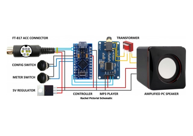 This construction project is for anyone wanting to give this popular little radio a voice of its own. This Speech synthesiser reads out the current frequency, mode and menu settings whenever they are changed via the front-panel controls
 -
 This document provides a detailed guide on constructing and mounting a folded dipol for the 146 MHz frequency in a vertical configuration to be used in Yagi antennas. The step-by-step instructions and diagrams included make it easy for hams to build and set up this type of antenna. Understanding and implementing this design can enhance the performance of radio communication for Amateurs operating in the 2-meter band. Whether you are looking to improve your signal strength or experiment with antenna designs, this resource offers valuable insights and practical information.
 -
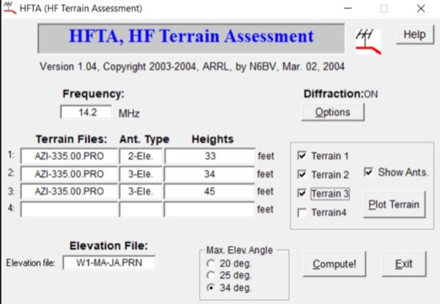 A complete guide to plan antenna installation by using several tools and resources including the popular HFTA High-Frequency Terrain Assessment software distributed by ARRL. A full tutorial on how to use it and how to interpretate reports produced by this antenna setup analysis tool.
 -
 A medium power End Fed Half Wave Antenna coupler, specifically tuned to the QRP frequency of 7030 kHz. Constructed from coil stock and capacitors, it achieves an impedance ratio of 64:1. The coupler has proven effective for power ranges from 2 to 100 Watts on the 40m band.
 -
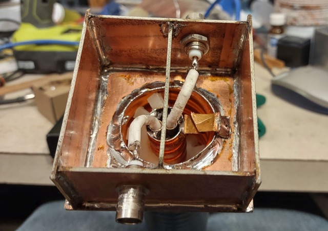 Cavity is often required at a busy site to not only prevent its receiver from being overloaded by off-frequency signals, but also be a good neighbour and prevent low-level signals from your transmitter from getting into other users receivers - not to mention the preventing of those other signal from getting back into your transmitter to generate spurious signals in its own right.
 -
 Presents two distinct hardware modifications for the Icom IC-7300 transceiver, detailing the necessary steps for each. The first modification, a _MARS_ transmit expansion, involves the physical removal of specific surface-mount diodes (D422) from the main board, enabling transmit capabilities across a broader frequency range, including out-of-band frequencies. It specifies the diode location on US versions of the IC-7300 and suggests using small diagonal cutters if a soldering iron is not preferred or available. The second modification focuses on the internal antenna tuner, aiming to provide wider impedance matching capabilities. This involves adding a **100k ohm** resistor to a designated point within the tuner circuit. The resource also briefly mentions a microphone modification for the _HM219_ and a general power increase, though without specific instructions for the latter two. It emphasizes safety precautions, such as disconnecting power and inspecting the work area.
 -
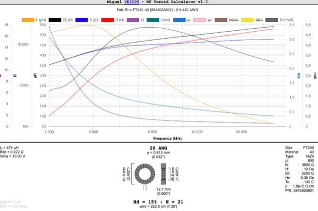 This RF Toroid Calculator provides graphical calculator used to determine the inductance and other parameters of ferrite and powdered-iron toroids. It simplifies the process of selecting the appropriate toroid for use in radio frequency (RF) circuits
 -
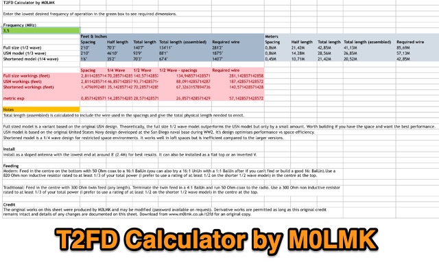 An Excel sheet calculator for the T2FD wire antenna. The sheet has been proved to work either on LibreOffice and Apple Numbers. Just input the resonating frequency to get the proper size and dimensions.
 -
 A Magnetic Loop Controller project details the construction and operation of an automatic tuning system for magnetic loop antennas, which are resonant circuits using an oversized inductor and an adjustable capacitor. The system employs a stepper motor to precisely adjust the variable capacitor, maintaining optimal resonance across the HF bands. It integrates with various transceivers, including _Icom_, _Kenwood_, and _Yaesu_ models, by monitoring the VFO frequency and adjusting the loop's tuning accordingly. The project provides comprehensive building instructions, a PowerPoint-style presentation, and the full source code for the controller's firmware, enabling hams to replicate and customize the design. The controller's firmware offers diverse functionality, including automatic frequency tracking, manual tuning, and SWR monitoring, significantly enhancing the operational efficiency of magnetic loop antennas, particularly for QRP and portable operations. The design emphasizes accurate capacitor positioning, crucial for achieving low SWR and maximum radiated power. Comparisons with manual tuning methods highlight the benefits of real-time adjustment, especially when operating across different bands or making frequent QSYs. The project's detailed documentation and available source code facilitate experimentation and modification by advanced builders, allowing for tailored performance characteristics.
 -
 This article describes the phases for the construction of a Yagi antenna. The calculations of the parameters are made using 4NEC2 software. This type of antenna is used for transmissions and receptions of electromagnetic waves. The project shown here refers to the frequency of 433.92 MHz.
 -
 Since 1988, Royal Communications International has been supplying communications equipment designed for the military, professional, and amateur market. We specialize in the sale and service of High Frequency, Single Sideband transceivers that are dependable and easy to use.
 -
 Online antenna calculator for a basic 3 elements yagi uda directional antenna. The described antenna design offers a front-to-back ratio of at least 20 dB, a gain exceeding 7.3 dBi, and a bandwidth (SWR < 2) of approximately 7% around the center frequency. It has an input impedance of 50 ohms when using a straight split dipole, which can be substituted with a folded dipole of the same length, increasing the impedance to 200 ohms. A matching balun is required for coaxial feeder connection, and the boom should be made of a dielectric material, like wood.
 -
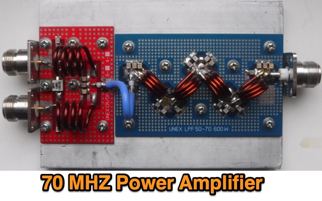 This PA has been designed by Sergey EX8MLE and uses three Mitsubishi RD100HHF1 FETs, Frequency Range 70 to 72 MHz
 -
 Four distinct amateur radio bands, specifically 40, 30, 20, and 15 meters, are addressed by a portable dipole antenna design. This antenna utilizes a manual switching mechanism, employing "fast-on" or flying connectors to change bands. The design is presented with an animated plan, illustrating how operators can adjust the operating frequency by opening and closing specific connections on the antenna elements. The resource describes a _4 savos dipol_ (4-band dipole) that can be shortened for specific band operation. It provides practical information for hams seeking to construct a versatile, multi-band wire antenna for portable operations or fixed station use. This design offers a straightforward approach to achieving multi-band HF capability without complex tuning units, making it suitable for field deployments like SOTA or POTA activations where rapid band changes are beneficial.
 -
 The J-pole antenna calculator helps users design custom J-pole antennas for specific frequency bands. It provides dimensions for key antenna sections based on the chosen frequency and material’s velocity factor. The calculator also offers insights into J-pole antenna mechanics, velocity factors, and mounting tips, making it ideal for enthusiasts creating antennas for amateur or mobile radio communications.
 -
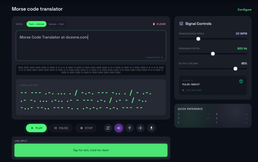
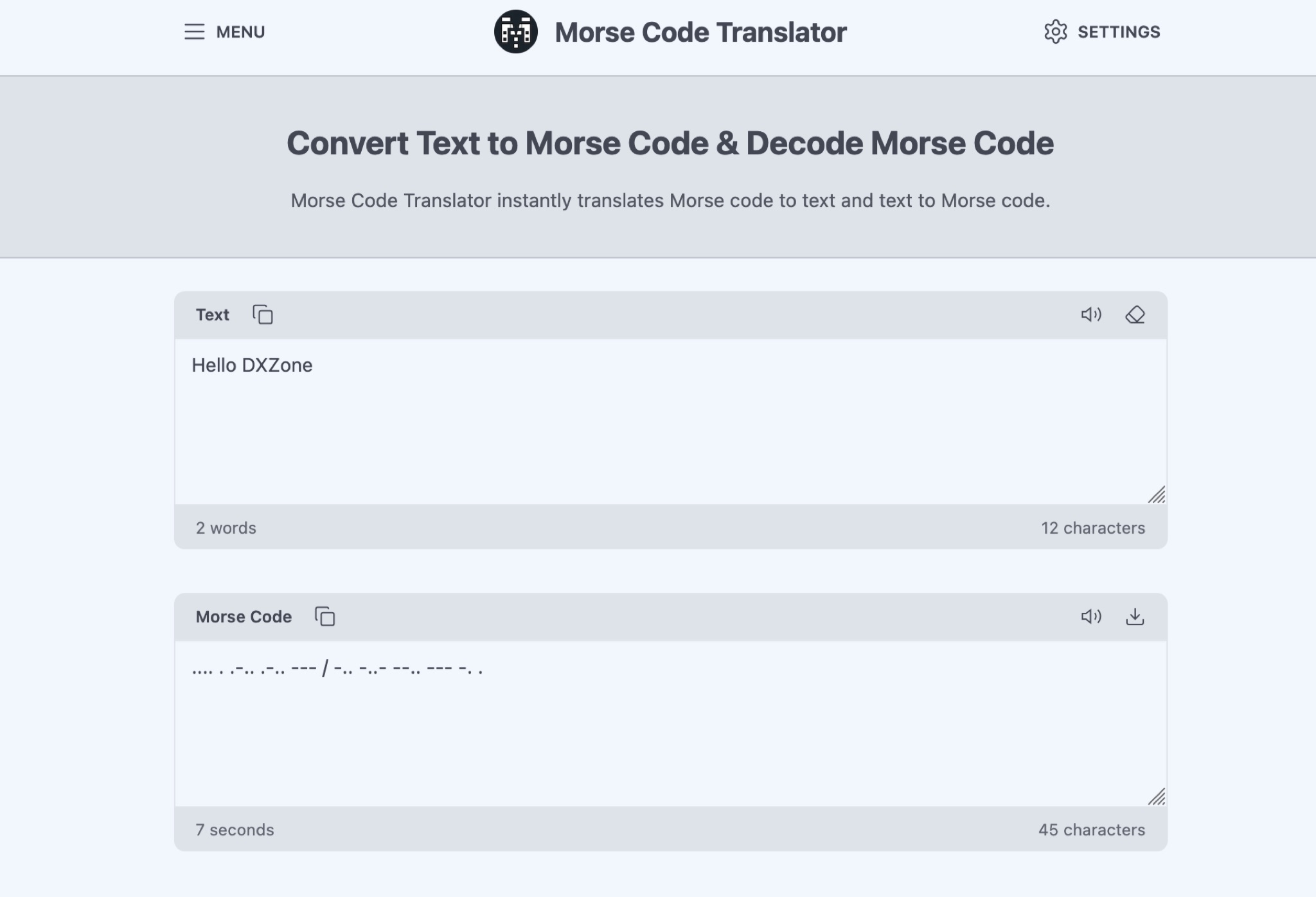 The Morse Code Translator allows anyone to easily convert text into Morse code and vice versa. Simply enter the text to translate or Morse code to decode. This tool is useful for amateur radio operators, scouts, educators, or anyone interested in learning Morse code for educational, professional, or recreational purposes. Discover hidden messages, learn the Morse code alphabet, and practice decoding signals. The tool offers advanced options like adjusting frequency, words per minute, characters, and spacing. Experience Morse code visually with the light translator. Explore the history and uses of Morse code, from military and emergency communications to fun secret messages among friends.
 -
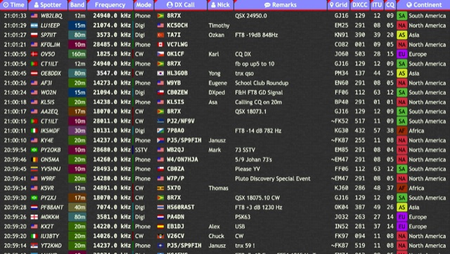 Over 15 amateur radio bands, from 160m to 70cm, are supported by the _DXTRON_ web cluster, providing real-time DX spotting information. This service integrates directly with the _QRZCQ_ API, allowing users to monitor activity across various modes including CW, Phone, Digi, RTTY, SSTV, and SAT. DXTRON displays critical spot data such as timestamp, spotter callsign, frequency, mode, DX call, and remarks, along with geographical details like Grid, DXCC, ITU, CQ zone, continent, and country. Developed by _DO5SSB_, DXTRON v1.42 offers a user-friendly interface for filtering spots by band and mode, catering to both casual DXers and serious contesters. The platform is designed for accessibility, providing a clear overview of current propagation conditions and active stations worldwide. This web cluster is a practical tool for hams seeking to identify rare DX, track contest activity, or simply observe band conditions. Its reliance on the QRZCQ API ensures a consistent flow of up-to-date spotting data, making it a reliable resource for real-time operational awareness.
 -
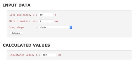 The high-frequency inductance of single-turn loops of various shapes made of round wire can be estimated accurately with a simplified formula
 -
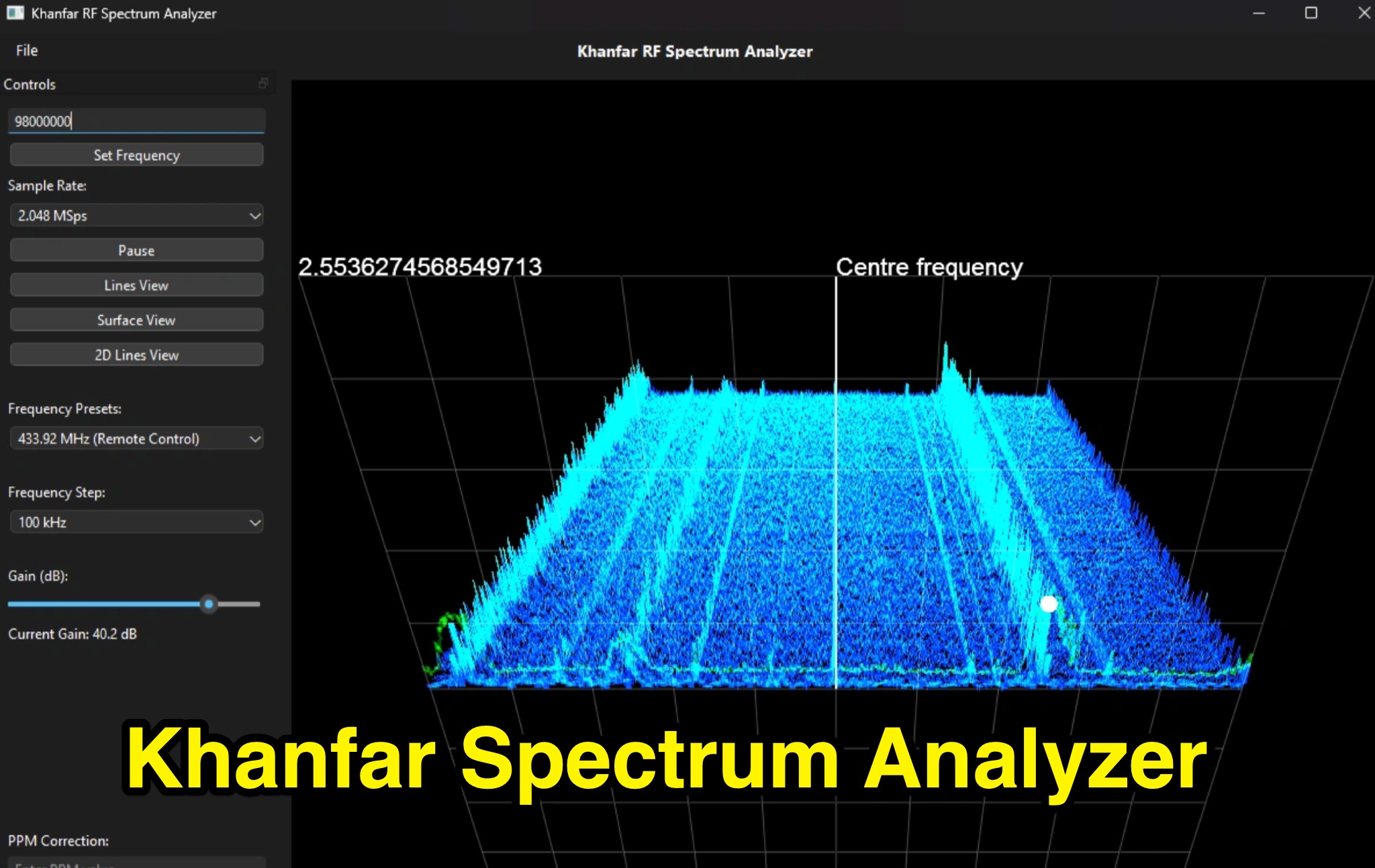 Professional SDR Signal Analysis Tools - Khanfar Spectrum Analyzer offers specialized SDR software tools for signal analysis, including real-time FFT analysis and precise frequency selection. The website provides a range of software for signal monitoring, spectrum analysis, radio direction finding, and antenna systems.
 -
 SkyRoof is an open-source, 64-bit Windows application designed for amateur radio operators and satellite enthusiasts, combining satellite tracking and Software Defined Radio (SDR) functionality in a unified platform. The software provides real-time satellite tracking, pass predictions, and visual representations through Sky View, Earth View, and Timeline displays. It features an SDR-based waterfall display covering VHF/UHF satellite segments with Doppler-corrected frequency scales, automatic satellite labeling, and visual tuning capabilities. SkyRoof supports various SDR devices (Airspy Mini, SDRplay, RTL-SDR), external transceiver CAT control, and antenna rotator integration. The application automatically downloads satellite data from SatNOGS and other sources, offers voice announcements for satellite passes, and includes comprehensive frequency control with Doppler tracking, manual corrections, and RIT functionality for enhanced satellite communication operations.
 -
 he LoRa-APRS-iGate was developed in cooperation with the Austrian HAM Radio Association. With this software and the LoRa GW Shield, devices transmitting on LoRa, frequency 433 MHz can be integrated into the APRS network. The transmitter can then be displayed on the website https://aprs.fi.
 -
 Microwave Filter Company is a leader in the design, development and manufacture of high quality passive electronic filter products in the 5 Hz to 50 GHz frequency spectrum.
 -
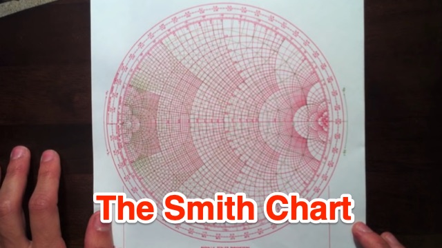 This tutorial introduces and explains Smith Charts, and then gives an introduction to impedance matching. Smith Chart is a tool to visualize the impedance of a transmission line and antenna system as a function of frequency.
 -
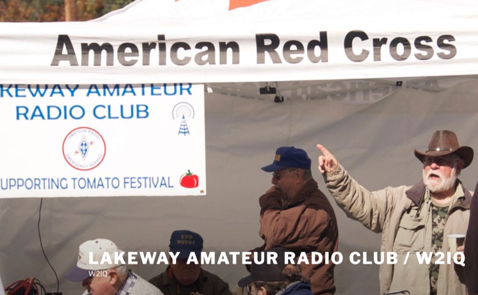 The Lakeway Amateur Radio Club, identified by its callsign _W2IQ_, serves as a significant hub for amateur radio operations within the Lakeway Area. This organization demonstrates a strong commitment to regulatory compliance and amateur radio accessibility through its robust Volunteer Examination (VE) Team. As an ARRL-accredited entity, W2IQ facilitates online FCC amateur radio licensing examinations, providing a critical service for new licensees to enter the hobby. This infrastructure supports the growth of the amateur radio community by streamlining the licensing process, making it highly accessible to prospective operators. The club's technical contributions extend to fostering diverse operational interests, though specific repeater or APRS infrastructure details are not explicitly detailed. Their emphasis on licensing and education, particularly through remote testing protocols, highlights a modern approach to amateur radio entry. This focus on **VEC protocol coordination** ensures a consistent pathway for individuals seeking to obtain or upgrade their amateur radio licenses. The club also promotes engagement with various aspects of the hobby, indicating a broad interest in amateur radio activities and technical development within its geographic sphere of influence. Their dedication to supporting new radio amateurs underscores a foundational role in regional frequency management and community building.
 -
 TFilter is a free online tool for designing linear phase, optimal, equiripple finite impulse response (FIR) digital filters. It utilizes the Parks-McClellan algorithm implemented in JavaScript. Users can specify the sampling frequency, desired number of taps, passbands, and stopbands to generate a filter. An example configuration is provided for easy testing.
 -
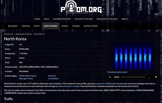 The resource details active HF radio networks maintained by foreign ministries for diplomatic communications, specifically listing operational schedules and frequencies. It currently covers networks for Bulgaria, Czechia, Egypt, North Korea, Russia, Tunisia, and the United States. The content provides specific operational parameters for these government-run shortwave stations. Information includes details on _legacy modes_ of operation and specific transmission times. The site also includes schedules for various _number stations_ which often utilize similar HF spectrum allocations. The data presented aids in identifying and monitoring these unique, non-amateur radio signals across the shortwave bands. Specific sections are dedicated to the networks of North Korea and the United States, offering granular data for each.
 -
 This project introduces the Loggi, a hybrid antenna merging the wide frequency coverage of log-periodic dipole arrays (LPDA) with the high gain and front-to-back ratio (F/B) of Yagi antennas. Traditional LPDAs span broad frequencies with moderate gain and low VSWR, while Yagis provide high gain and F/B over narrow bands. By analyzing high-Tau LPDA designs, it was found they could nearly match the gain of VHF/UHF Yagis while maintaining excellent patterns, F/B, and front-to-rear ratios (F/R). Optimizing specific elements for target frequencies (e.g., 144.1 MHz) led to the Loggi, which uniquely features all driven elements without passive directors or reflectors. This design effectively functions as a narrowband optimized LPDA, with front elements acting like Yagi directors and rear elements like Yagi reflectors, thus enhancing gain and directional characteristics while retaining broad frequency versatility.
 -
 A homebrew spectrum analyzer, the Specan, provides a crucial measurement capability often missing from the typical amateur radio shack, allowing for detailed analysis of RF signals up to 70 MHz. This double-conversion superheterodyne receiver design incorporates 112 MHz and 12 MHz intermediate frequencies, utilizing an _Si570_ as the local oscillator for fine tuning down to 1 Hz steps. It offers two resolution bandwidths: 300 KHz for broad spectrum sweeps and 1 KHz for precise close-in distortion measurements, achieving an 80 dB spur-free dynamic range at 1 KHz resolution. The project, a reboot of the classic _W7ZOI/K7TAU_ design from November 1998 QST, integrates an _Arduino_ microcontroller for controlling the Si570, managing a front-panel LCD, and communicating with a PC for spectrum plotting. This approach significantly reduces cost compared to commercial units, making advanced RF diagnostics accessible to homebrewers. The Specan can measure carrier suppression, VFO cleanliness, antenna VSWR, transmitter harmonics, and filter passband shapes, providing insights beyond what an oscilloscope or frequency counter can offer. Construction emphasizes modularity and careful shielding, with each stage built and tested individually on unetched copper clad board. The design includes detailed instructions for integrating the Arduino, building the Si570 oscillator, and aligning the various modules, often using the Specan itself for calibration. It requires a well-regulated linear power supply and can be built with common tools and readily available components, making it a practical and rewarding endeavor for those looking to enhance their RF test bench.
 -
 The multiband tuned doublet, or center-fed Zepp, is a simple and efficient HF antenna that operates effectively across most amateur bands using a balanced parallel-wire feedline and antenna tuner. Unlike coax-fed dipoles, it tolerates impedance mismatches with minimal loss. By selecting suitable feedline and dipole lengths, one can achieve stable multi-band operation. While it doesn’t match monoband Yagis, it offers excellent performance, low cost, and broad coverage. Its radiation pattern and efficiency vary with frequency, but it remains a practical and versatile solution for HF operators.
 -
 Showcasing German engineering, ANjo Antennen develops and manufactures a diverse portfolio of amateur radio and commercial antenna products. Their offerings span a wide frequency range from 1.8 MHz to 3000 MHz, emphasizing electrical and mechanical precision for longevity. The company actively participates in events like FUNK.TAG Kassel, providing opportunities for direct engagement and order pickup. ANjo's product line includes high-performance **Yagi antennas** optimized for Tropo and EME, along with multi-stacked Quad antennas designed for contest operations, featuring wide horizontal and narrow vertical beamwidths. They also produce circularly polarized satellite antennas, some with switchable LHCP/RHCP, leveraging their commercial satellite antenna expertise. Beyond amateur applications, ANjo provides flexible, custom antenna solutions for commercial sectors such as BOS, EMC measurements, and telemetry. Their commitment to quality is evident in the Premium-Line antennas, which utilize **1.4301 (V2A) stainless steel** for mast clamps and connectors, ensuring durability and corrosion resistance. They also offer end-fed HF multiband wire antennas, known for their compact footprint and discreet installation.
 -
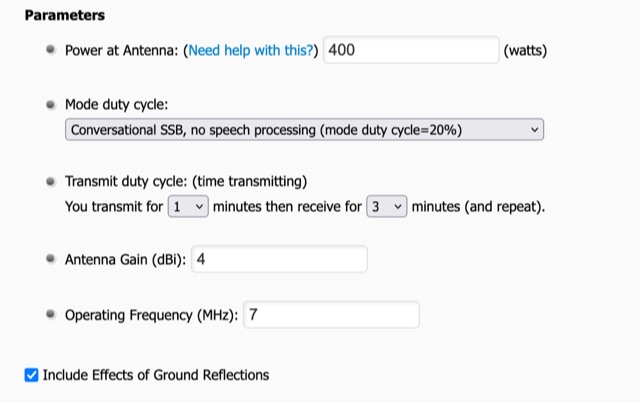 To use the RF Exposure Calculator, fill-in the form with your operating power, antenna gain, and the operating frequency. Depending on how far above ground the RF source is located, you might want to consider ground reflections too.
 -
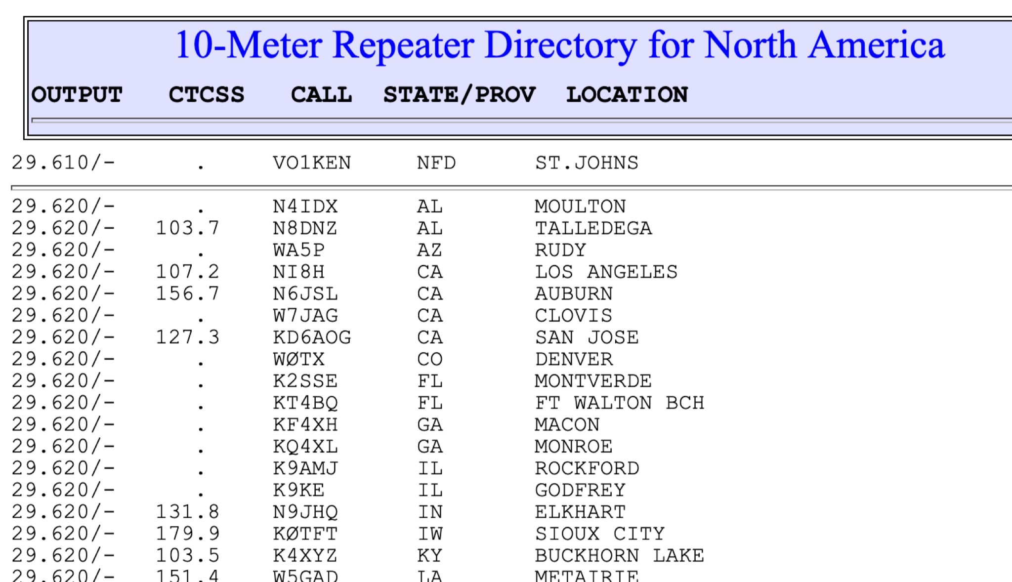 This page show a list of repeaters in north america transmitting from 28 MHz to 29 MHz. The most of them are in the 29.620 to 29.700 frequency range. Some repeaters may be active and on the air while others may not
 -
 This project delves into the development of a compact WSPR beacon, building on earlier experiences with weak-signal modes. Inspired by QRP Labs kits and modified open source designs, it integrates a Si5351 frequency generator, GPS module, and class E PA for efficient operation. Extensive optimizations—addressing drift, heat management, and power stability culminated in a portable, serviceable device. The beacon offers insights into propagation while minimizing reliance on main station equipment. Lessons learned highlight the importance of careful component selection and iterative design improvements for robust amateur radio experimentation.
 -
 This page provides construction details for a 4-element 10-meter Yagi antenna with 28 Ohm impedance. It includes information on the elements, positions, diagrams, and data related to frequency, gain, front-to-rear ratio, radiation resistance, SWR, and loss. The content is aimed at hams or radio operators interested in building and optimizing Yagi antennas for the 10-meter band.
 -
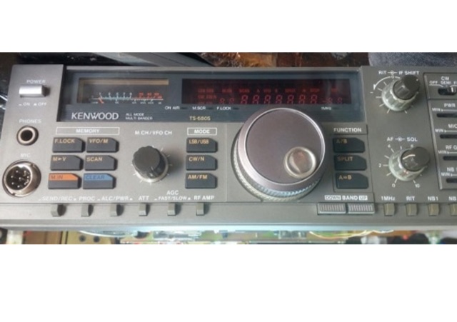 Extend frequency coverage on the Kenwood TS-680S transceiver