Search results
Query: signal 5
Links: 766 | Categories: 52
Categories
- Technical Reference > RF Signal Generators
- Manufacturers > Test Equipment > Signal generator
- Software > Signal Generator
- Technical Reference > Test Equipment > Signal Generator
- Software > Weak Signal
- Operating Modes > Weak Signal
- Shortwave Radio > Broadcasters > Time Signal Radios
- Antennas > Active
- Technical Reference > AI Ham Radio
- Operating Modes > Aircraft scatter
- Operating Modes > Amateur Television
- DX Resources > Beacons > Beacon Monitoring
- Antennas > Collinear
- Software > Decoders
- Operating Modes > Satellites > Digital Satellites
- Software > Digital SSTV
- Software > DRM
- Operating Modes > DSP
- Software > DSP
- Technical Reference > Filters
- Operating Modes > FT8
- Radio Equipment > HF YAGI Antennas
- Antennas > Theory > Impedance matching
- Software > JT65
- Operating Modes > JT65
- Operating Modes > JT9
- Technical Reference > Key Clicks
- Antennas > Lindenblad
- Propagation > Long-Delayed Echoes
- Radio Scanning > Nature
-
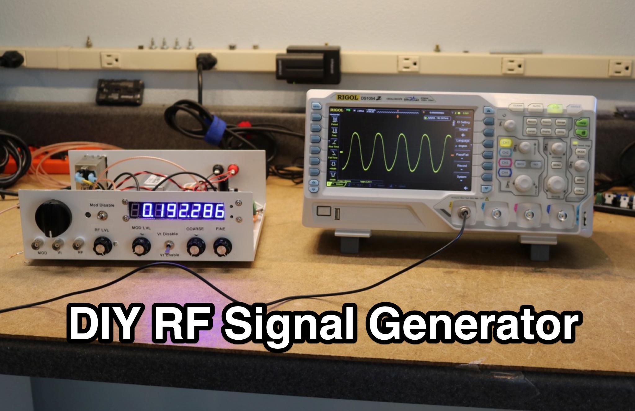 Learn how to build your own RF signal generator for aligning radios by following the modifications made to the circuit of an existing project. Explore the use of a common cathode varactor diode and a single center-tapped 24 VAC transformer to simplify the design. Discover alternative components like the MACOM 4ST079CK-287T varactor diode, which offers cost-effective solutions compared to unobtainable options. Find inspiration in modifying existing projects and gaining practical knowledge in electronics. Purchase the Nuts and Volts magazine for detailed schematics and a deeper understanding of RF signal generators.
 -
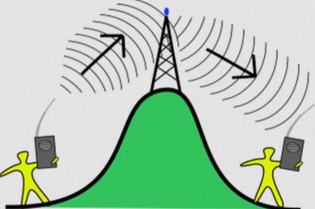 The most basic form of repeater receives communication on one frequency and re-transmits it on a different frequency, a process known as duplex communication. This capability significantly extends the range of handheld and mobile radios, as repeaters are typically situated at elevated locations with high-gain antennas and greater transmit power. Repeaters commonly operate with FM modulation on the VHF (30 MHz – 300 MHz) and UHF (300 MHz – 3 GHz) amateur bands, which are ideal for portable and mobile devices. Access to repeaters is often controlled by a CTCSS or PL tone, an inaudible signal that prevents the repeater from retransmitting background noise. This mechanism ensures efficient use of the frequency and prevents illegal continuous transmission. Canadian regulations, for instance, require an Advanced amateur radio license and an available frequency within the band to set up a repeater, each assigned a unique call sign and transmit frequency. Configuring a radio for repeater use involves knowing the repeater's transmit frequency, its receive frequency offset (e.g., -600 KHz for VHF or +5 MHz for UHF), and the necessary CTCSS tone. The article references resources like Repeater Book for locating repeaters and provides practical examples for initiating and concluding a basic repeater session, emphasizing clear identification and concise communication.
 -
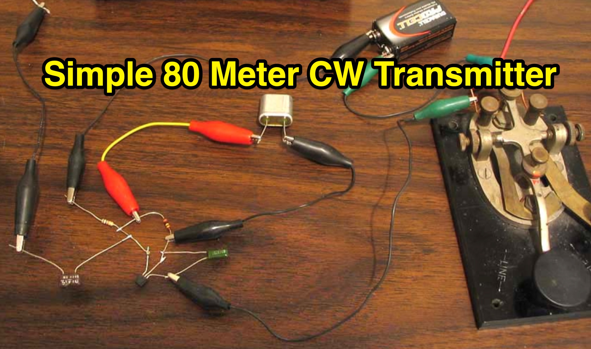 Learn how to build a simple transmitter called the 'Easy Ten' that can be easily heard at a distance of 10 miles using a random length wire antenna thrown into a tree. This article focuses on working with frequencies in the 3.5 and 7 MHz range without the need for complex setups like coax lines or baluns. The author shares their experience of making contacts across the Pacific Ocean and the United States using just one watt of output power and simple antennas. Discover how to optimize signal output using a homemade level meter made from a DC microameter and a germanium diode.
 -
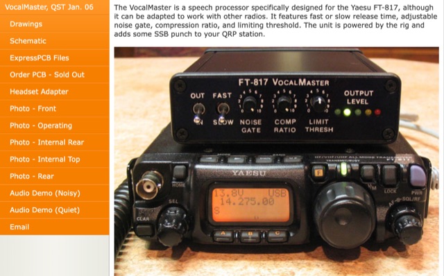 Inspired by Heathkit, author aimed to enhance his Yaesu FT-817 with audio and RF processing. Design goals included a compact enclosure, PCB simplicity, matching jacks, a visual meter, and a built-in signal generator. Despite challenges in finding a suitable compressor IC for a 5V DC mic jack, he chose the Analog Devices SSM2165/2166 series. Prototyping with a solderless breadboard, author planned a PCB layout for its versatile performance in communication use.
 -
 From March 2 to March 11, 2018, a Norwegian team operated as Z2LA from Zimbabwe, focusing on 160m through 10m bands using SSB and CW modes. The operation, described as "holiday style," aimed to provide contacts for DXers worldwide seeking a rare DXCC entity. Key equipment included a SUNSDR PRO II, an Elecraft KX3, and an Icom 706 MK2G as a spare radio, supported by two Juma 1000 amplifiers for robust signal output across the bands. Antenna systems were tailored for multi-band operation, featuring an Inv L for 160m and 80m, sloping dipoles for 30m/40m, and a _Hexbeam_ from SP7IDX Technology covering 20m to 10m. For improved reception, the team deployed a SAL 30, two reversible BEV antennas from remoteqth.com, and a BOG from K1FZ, enhancing their ability to hear weak signals. QSL information directs operators to Clublog for log search and M0OXO Charles for OQRS, explicitly requesting no bureau cards. The team comprised LA7THA Rune, LA7WCA Arne, and LA9VPA Thor, successfully making numerous contacts and contributing to the DX community's pursuit of _Zimbabwe_ as a DXCC entity.
 -
 Chavdar Levkov, LZ1AQ, presents an experimental comparison of small wideband magnetic loops, building on his previous work on wideband active small magnetic loop antennas. His research focuses on increasing loop sensitivity by maximizing the short-circuit current, which is directly tied to the "loop factor" M = A/L, where A is the equivalent loop area and L is its inductance. Levkov's methodology involves reducing inductance and increasing area through parallel or coplanar crossed (CC) configurations, comparing these designs against a reference single quad loop of 1 m2 area. Experimental verification included testing three distinct loop types: a simple quad loop, two coplanar crossed (CC) loops, and eight parallel loops, all designed to have a total geometric area of 1 m2. Measurements were conducted at 1.8, 3.5, 7, and 10 MHz using a small transmitter 270 meters away, with a Perseus direct sampling receiver for precise signal level assessment. The results consistently showed that CC loops, particularly Loop 5 (two CC circular loops with 1.44 m2 total area), yielded significantly higher currents, up to 9.1 dB over the reference loop at 3.5 MHz, validating M as a reliable predictor of loop sensitivity. Numerical simulations using MMANA further corroborated the experimental findings, demonstrating an almost perfect correlation between the calculated M factor and the induced loop current for 15 different loop models. Levkov concludes that CC loops offer superior sensitivity for a given loop area, while parallel loops are advantageous for minimizing physical volume. Practical recommendations suggest using loops with an M factor greater than 0.5 uA/pT for quiet rural environments, and he provides a spreadsheet tool, WLoop_calc.xls, to aid in optimizing loop configurations for specific operational needs.
 -
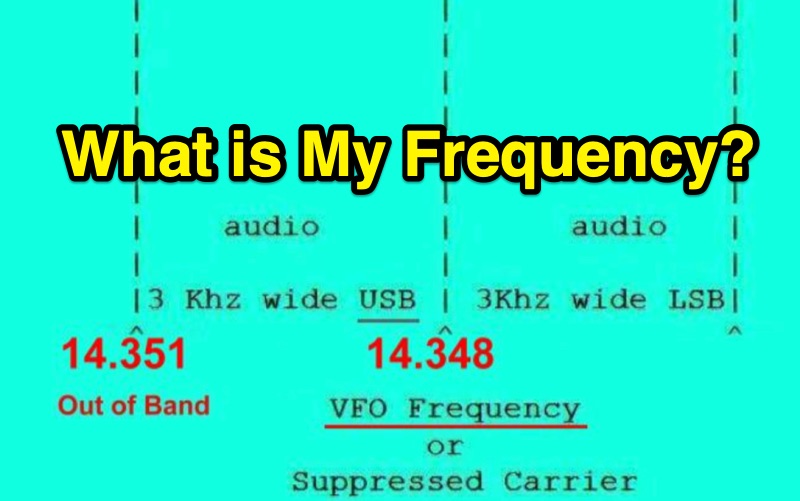 Single Sideband (SSB) operation requires careful attention to the relationship between a radio's displayed frequency (suppressed carrier) and the actual 3 kHz wide audio signal. This resource clarifies how Upper Sideband (USB) and Lower Sideband (LSB) signals occupy spectrum above or below the indicated frequency, respectively. It provides practical examples for General Class operators on the **20m** and **40m** bands, such as setting a VFO to 14.226 MHz for USB on 20m or 7.178 MHz for LSB on 40m, to maintain a safe margin from band edges. The resource emphasizes the critical importance of staying within allocated band limits to prevent out-of-band emissions, particularly when operating close to band edges. It includes relevant excerpts from **FCC Regulation Part 97**, specifically section 97.307, which details emission standards, necessary bandwidth, and spurious emission attenuation requirements. The text explains that unused sidebands are considered spurious emissions and notes that modern HF equipment typically exceeds the 43 dB spurious emission reduction standard, often achieving 60 dB or more.
 -
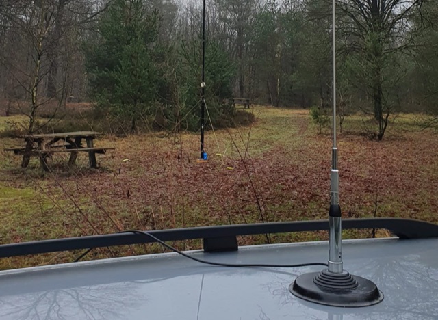 PH0NO conducted field tests comparing a mobile antenna (DX-UHV) to an end-fed half-wave wire. Results on 20m showed the end-fed wire outperforming the mobile antenna, with a significant difference in signal strength. On 40m, the end-fed wire surpassed the mobile antenna in spots and reach. While the mobile antenna is more practical, the end-fed wire offers superior performance. Further testing is planned.
 -
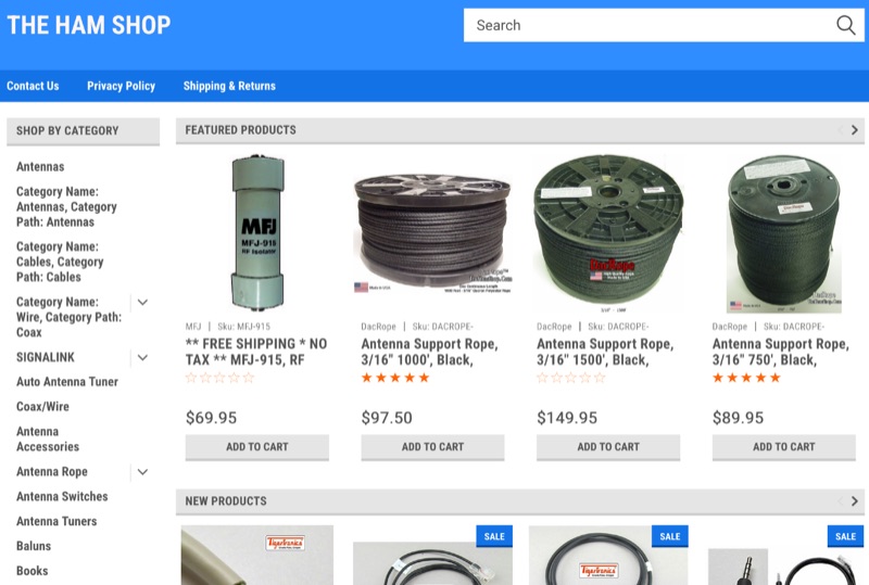 The _MFJ-915_ RF Isolator, rated for 1.8-30 MHz and 1500W PEP, exemplifies the product range available from The Ham Shop. The inventory includes various antenna support ropes, such as 3/16" _Dacron Polyester Rope_ in lengths from 100 to 1500 feet, alongside a selection of cables for _SignaLink USB_ sound card interfaces. Specific SignaLink cables are offered for radios like the Yaesu FT-847 (SLCAB847), Yaesu HTs (SLCABVXY), and the Elecraft K3 (SLCABHTY). Additionally, the shop provides modular jumper cables and modules, including the SLMOD8RY for Kenwood/Alinco 8-pin round mic jacks and the SLMOD8RI for Icom 8-pin round mic jacks. The product line supports diverse station configurations, encompassing antennas, coax, baluns, dummy loads, duplexers, insulators, microphones, power supplies, SWR meters, and watt meters.
 -
 This document provides comprehensive guidance on modeling and constructing multiband dipole antennas using traps. It addresses common segmentation issues in EZNEC modeling software, recommends optimal segment lengths for trap models, and compares trapped dipoles with paralleled multiband dipoles. While trap dipoles are significantly shorter, they exhibit lower gain and narrower bandwidth. Detailed instructions for building weatherproof coaxial traps include material lists, construction steps, and tuning methods. The guide notes that properly constructed coaxial traps introduce only minimal signal loss (0.6 dB) while offering practical multiband performance in a compact design.
 -
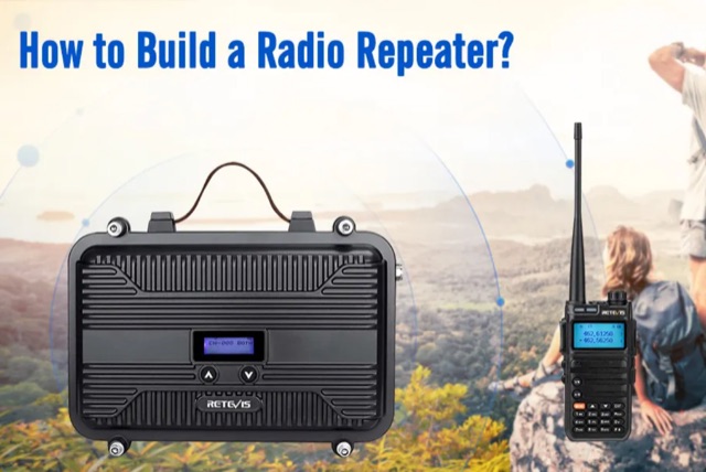 Building a radio repeater enhances communication by extending signal range and overcoming obstacles like mountains or buildings. This guide explains the fundamentals of radio repeaters, their function, and a step-by-step DIY approach. Key steps include conducting a site survey, selecting an optimal installation location, and configuring the system with suitable equipment such as the Retevis RT97 series. Proper placement, antenna setup, and testing ensure effective operation, making this process accessible for enthusiasts aiming to improve communication reliability and range
 -
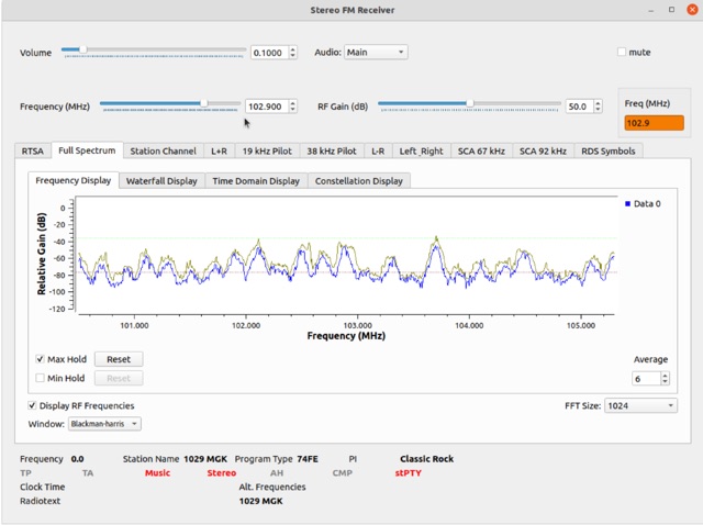 This document outlines various miniature projects undertaken by Mike Markowski to enhance his skills in GNU Radio. Key projects include an FM stereo receiver and an AM radio receiver, featuring advanced functionalities like pilot tone recovery and RDS integration. Additional experiments involve generating Gaussian noise, chirp signals, and Morse code decoding, emphasizing hands-on learning and customization in GNU Radio. The author encourages feedback and shares flow graphs and Python code for each project, aiming to foster community engagement and knowledge sharing.
 -
 This article focus on the radiation angle of vertical antennas and the fundamentals of electromagnetic wave propagation. The calculation of antenna length at 145 MHz is followed by an explanation of electromagnetic wave speed and the link between wavelength, frequency, and velocity. Author discusses the 5/8th wave vertical antenna, namely its performance and the influence of radiation angle on signal transmission. Figures and analogies demonstrate how different antenna types produce distinct radiation patterns. This highlights the importance of selecting the right antenna for a certain purpose, such as local traffic or dxing. The article discusses a variety of factors that affect antenna performance, including SWR, propagation conditions, and equipment dependability
 -
 The article discusses the evolution of antenna designs, specifically focusing on the upgrade from the W7IUV rotatable Flag to the Waller Flag. Author Pierluigi Mansutti IV3PRK shares insights on modeling these antennas using EZNEC software, detailing their performance in noisy environments. The W7IUV Flag proved effective for receiving signals, while the Waller Flag, developed by NX4D and N4IS, offers improved front-to-back ratios but requires careful consideration of signal levels and noise management. The article emphasizes practical modeling results and interactions between different antenna setups.
 -
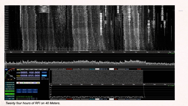 Demonstrates the application of Software-Defined Radios (SDRs) as effective tools for conducting Radio Frequency Interference (RFI) site surveys. The resource details the methodology for capturing and analyzing RFI, specifically focusing on the 80-meter band over a 24-hour period. It outlines the setup of an SDR-based survey tool, utilizing software like _S-Meter Lite_ and _Spectrum Lab_ to visualize and quantify noise sources. The article emphasizes the SDR's wideband capabilities, which allow for comprehensive identification and documentation of RFI across broad frequency ranges, crucial for effective mitigation strategies. The analysis presents practical results, illustrating how continuous monitoring can reveal intermittent RFI sources that might otherwise go undetected. For instance, the survey identified noise peaks exceeding **S9+20dB** on 80 meters during specific hours, correlating with local appliance usage. The methodology provides a repeatable process for hams to characterize their local noise floor, enabling targeted RFI suppression efforts and improving weak-signal reception, particularly for DXing and contesting.
 -
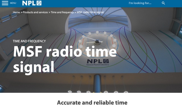 The MSF radio signal is a dedicated standard-frequency and time broadcast that provides an accurate and reliable source of UK civil time. It is available 24 hours a day across the whole of the UK and beyond. The signal operates on a frequency of 60 kHz and carries a time and date code that can be received and decoded by a wide range of readily-available radio-controlled clocks.
 -
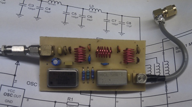 This article describes an HF upconverter for the FunCube Dongle Pro. Designed for radio amateurs, the converter extends reception capabilities to lower frequencies (0 Hz to 30 MHz) by mixing them with a higher oscillator frequency (100 MHz). This translates the desired signal into a range detectable by the FunCube Dongle (64 to 1,700 MHz). Key components include a double-balanced mixer and a low-pass filter to suppress unwanted signals. The project provides schematics, filter specifications, and design considerations for construction.
 -
 This PDF file provides detailed information on HF propagation for ham radio operators. It covers the principles of how radio signals travel over long distances, including factors that affect signal strength and propagation. The content is useful for hams looking to improve their understanding of radio communication and optimize their transmissions. Whether you're a beginner or an experienced operator, this resource offers valuable insights into HF propagation that can enhance your communication skills and efficiency on the airwaves.
 -
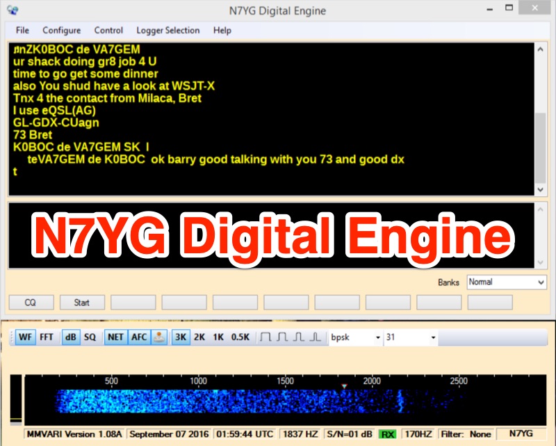 The N7YG Digital Engine, functions as a streamlined digital modem, supporting **PSK**, **RTTY**, and **MFSK** modes. It eliminates many ancillary logging and awards features found in other software, focusing instead on providing a dedicated digital interface. The software is specifically engineered to complement the N3FJP logging suite, offering a simple digital modem with a floating waterfall display that can coexist on the same screen as the logger. The application includes support for PSK Reporter, EXTFSK, TinyFSK, and K1EL Winkey FSK, enhancing its utility for various digital operations. Key features comprise a separate waterfall window, a main GUI with operational controls, receive and transmit display areas, and 10 Macro Buttons across 10 user-definable macro banks, totaling 100 macros for general and contesting use. Configuration options include sound card selection, digital gain (0-32767), AFC Level (0-100), AFC Width (in Hz), and COM Port TX keying for VOX/SignaLink or direct port control. Input and Output Mixer buttons provide direct access to OS audio mixer controls for precise level adjustments. The software is digitally signed with a security certificate, aiming to prevent conflicts with antivirus programs.
 -
 Noise-canceling electret condenser microphones (ECMs) are ideal for compact, battery-powered devices due to their small size, low power consumption, and high sensitivity. These microphones, used in conjunction with active noise cancellation circuitry, significantly reduce ambient noise, creating a more peaceful listening experience by combining and processing signals from multiple microphones.
 -
 Compare the efficiency of two HF (or VHF) antennas by simultaneously transmitting FT8 on nearly the same frequency and analyzing PSKReporter SNR data. Determine the effectiveness of your new antenna compared to the old one in dB, to several decimal places. Run FT8 on two transmitters with different call signs and equal power, connected to each antenna. AntennaCompare analyzes global signal reports, isolating antenna performance.
 -
 **APRS TX I-Gate with APRX and the Universal Radio Controller** This project explores the creation of an APRS TX I-Gate to improve message delivery in amateur radio communications. Initial experiments involved configuring a picoAPRS v4 and later a G1LRO Universal Radio Controller (URC) with a Quansheng UV-K5 as digipeaters. While both setups successfully retransmitted signals, they failed to receive incoming APRS messages. To address this, a Raspberry Pi Zero running Debian and APRX-2.9 was repurposed to provide network connectivity, transforming the URC into an effective TX I-Gate for seamless APRS message handling.
 -
 This project details the development of a modular direct conversion (DC) receiver designed for experimental flexibility in amateur radio and HF signal listening. The mainframe integrates a diplexer, DBM, and AF amplifier, supporting interchangeable local oscillator and antenna filtering setups. A tunable passive HF preselector complements QRP Labs bandpass filters for enhanced signal reception. Utilizing a NanoVNA for precise tuning, the receiver achieves improved signal-to-noise ratios across amateur and non-amateur bands, making it a versatile platform for further RF experimentation.
 -
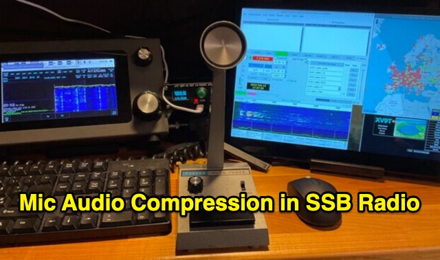 Single-sideband (SSB) radio enhances spectral efficiency but poses challenges with audio intelligibility, particularly in noisy conditions. A microphone audio compressor addresses these issues by dynamically managing the audio signal’s dynamic range. It amplifies quiet sounds and attenuates loud ones, ensuring consistent audio levels for improved clarity. Benefits include increased intelligibility, higher average power, and reduced spurious emissions. While essential for optimal SSB performance, careful parameter adjustment is crucial to balance natural sound quality and effective communication across various operating modes.
 -
 The F6AOJ RX splitter project was created to split the antenna signal from an LZ1AQ receive loop to multiple receivers, such as radios or SDRs. The design is simple to build and effective. The splitter, mounted on the back of the LZ1AQ control board, provides two outputs—one for an Afedri SDR and another for a K3 transceiver. Measurements show a damping of -3.01 dB at 1 MHz and -3.10 dB at 30 MHz, with a low SWR (max 1.07 at 30 MHz and 1.4 at 60 MHz).
 -
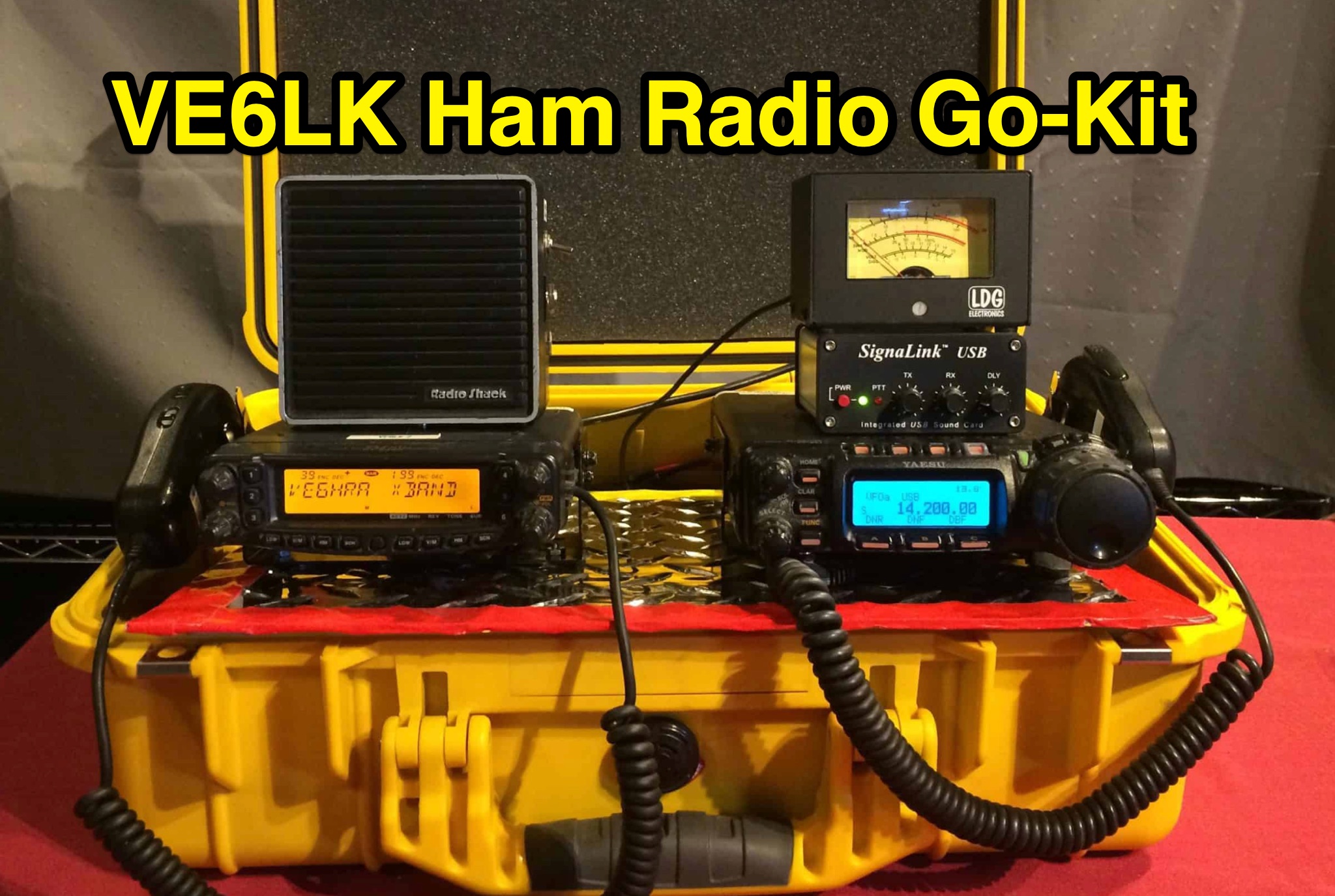 Learn how VE6LK built a comprehensive radio go-kit for emergency communication purposes. The kit includes Yaesu FT-8800, Yaesu FT-857, LDG FT-Meter, Powerwerx SS-30 power supply, SignaLink USB interface, and more. The author shares details on the equipment, organization, and practical tips for setting up the kit. Discover how to stay prepared for public service events, disaster responses, and general ham radio activities with a well-equipped go-kit.
 -
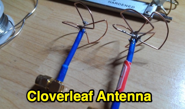 Cloverleaf antenna is a circular polarized antenna which is way better than the cheap dipole antenna that comes with video transmitters and receivers. The Cloverleaf is a closed loop antenna which the signal and ground wires are connected. The cloverleaf antenna has 3 loops at 120 degree apart, and they are titled at 45 degree to horizontal plane.
 -
 Learn how to hack an IR turret to track the International Space Station (ISS) as it passes overhead. Discover the basics of the ISS and how to use simple tools to point an arrow at the ISS without looking at a phone. Find out how to calculate the azimuth and elevation angles to locate the ISS in the sky and enjoy watching this habitable space craft orbit the earth at a speed of 28,000 km/h. Take your hobby to the next level by bouncing radio signals off the ISS or even talking to the astronauts on board. Turn stargazing into an interactive and educational experience with this fun and practical project.
 -
 Understanding radio wave propagation is fundamental for effective HF communication, and this guide from the Galway Radio Club elucidates the principles behind _Near Vertical Incidence Skywave_ (NVIS) operation. It begins by contrasting NVIS with line-of-sight and surface wave propagation, highlighting its utility for reliable regional coverage, particularly in challenging terrains or within the skip zone. The document explains how NVIS leverages high-angle radiation, refracting signals from the ionosphere to return to Earth within a circular region, typically up to **650 km** (400 miles) from the transmitter. The guide delves into critical factors influencing NVIS, such as the _critical frequency_ (Fo) and the Maximum Usable Frequency (MUF), emphasizing their dependence on solar activity, time of day, and season. It provides practical advice on frequency selection, noting that 40 meters is often the highest daytime NVIS band, with 60 meters and 80 meters favored as darkness falls. The author, EI5DD, suggests using an ionogram for real-time propagation data, considering it more reliable than generic ham-clocks. Antenna considerations are also covered, recommending dipoles, inverted vees, or phased dipoles positioned 0.1 to 0.25 wavelengths above ground for optimal high-angle radiation. The document mentions mobile NVIS setups, including military configurations and commercial options like the Barrett Communications roof-rack antenna, which can cost around **£2000.00**. It concludes by reinforcing NVIS as an essential technique for national emergency communications, with 5 MHz (60m) and 80 meters being primary bands for daytime and nighttime operations, respectively.
 -
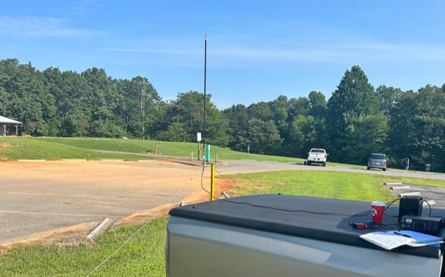 In his POTA activation, WK4DS experimented with radials for hamstick antennas. Despite sun and RF noise challenges, successful connections were made. Surprisingly, tuned radials proved unnecessary, simplifying setup. Hamsticks demonstrated versatility across frequencies. Increased power improved signal quality, sparking his curiosity for further exploration in radio technology.
 -
 Effective suppression of harmonics and parasitic radiation from HF transmitters is crucial, especially with the increasing sensitivity of VHF/UHF radio channels to interference. This project details a hybrid low-pass filter (LPF) designed to operate across the HF bands up to 51 MHz, making it suitable for 6-meter band operations while providing deep VHF/UHF suppression. The design addresses the challenge of modern interference landscapes, where even microvolt-level signals can disrupt wireless sensors and other simple VHF/UHF receivers. The filter utilizes a single elliptic link, combining high cutoff steepness with robust suppression in the hundreds of megahertz range. A key feature is the use of only two standard capacitor values, simplifying construction and component sourcing. The article provides a detailed schematic, performance characteristics, and _RFSim99_ model file, demonstrating a reflection coefficient S11 below 0.017 (VSWR < 1.03) across 1-51 MHz, ensuring minimal degradation to the antenna system. Construction notes include coil winding specifications and capacitor selection guidance, with recommendations for _FR-4_ assembly. Two capacitor sets are presented, with the first variant recommended for its lower RF current demands, keeping currents below 3 A at 1 kW passing power at 51 MHz. Fine-tuning involves adjusting frameless coils, with considerations for capacitor tolerance and high-frequency capacitance measurement accuracy.
 -
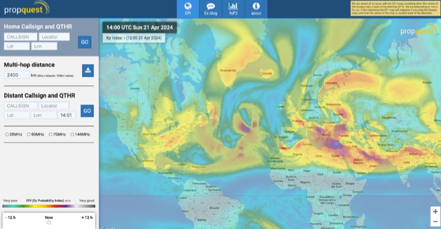 This website explains signal variations on a local radio net by tracking the foF2, a measure of ionosphere's ability to reflect radio waves. The website shows daily foF2 variations and how it affects Near Vertical Incidence Skywave (NVIS) propagation for local nets. It also considers D-layer absorption affecting lower bands and F2 MUF distance for long-distance communication. Additionally, the website tracks foEs for E-layer propagation and an EPI index for predicting Es chances.
 -
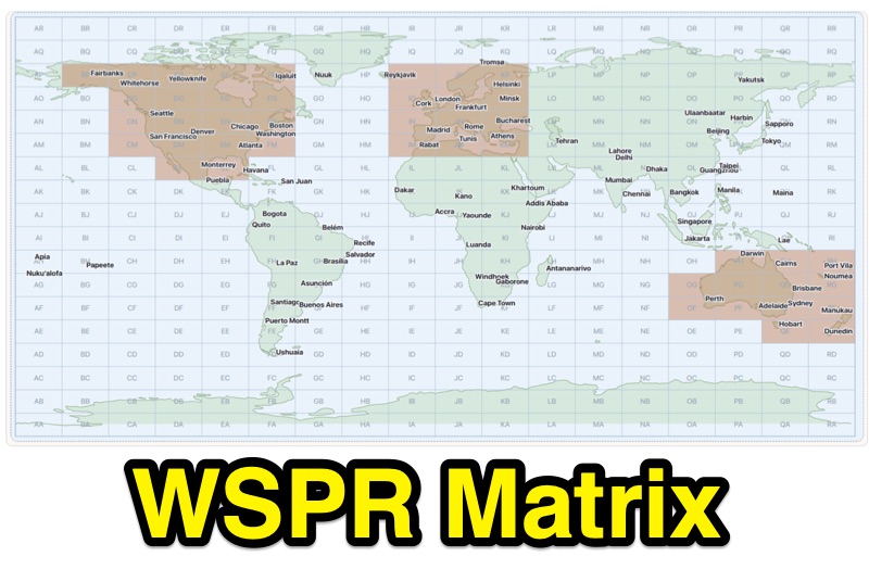 Demonstrates WSPR propagation activity, presenting observed data by reporter, band, UTC time, local time, and user-selected global destination areas. The application allows users to analyze WSPR spots from a live data server or import saved WSPRnet query files, bypassing the 10,000-row download limit by collecting individual band files for busy bands. Users can configure band preferences and destination modes, choosing between city radius or Maidenhead map grids for filtering path destinations. The interface provides options to start current-day live collection, a 7-day continuous archive, or load previously saved data to build the propagation matrix. Diagnostic information and archive history are accessible, alongside map setup controls for grid contrast and visibility. The tool supports both Path 1 and Path 2 map destinations, enabling detailed analysis of WSPR signal paths.
 -
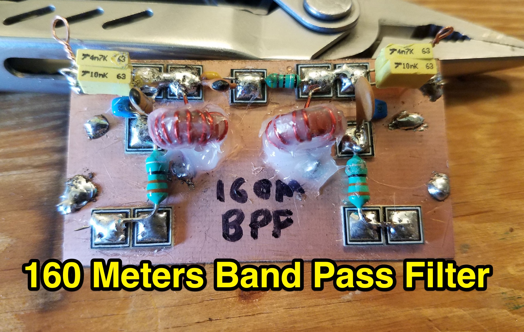 Learn how to enhance your 160 meter reception by building and using a custom band pass filter. Discover how this filter can reduce interference from strong AM broadcast signals, improving the overall performance of your receiver. Find out about the challenges of creating a filter that balances signal loss and attenuation at specific frequencies, and how it can benefit hams operating near powerful transmitters. Whether you're experiencing IMD issues or looking to optimize your 160 meter setup, this article provides practical insights and solutions for ham radio operators.
 -
 The Acom 1500 HF+6M Linear Amplifier is a high-quality and user-friendly amplifier that provides excellent performance and reliability. G6NHU, who previously owned an Acom 1000, upgraded to the Acom 1500 after nine years and has been using it for about eighteen months. Key features highlighted include the ability to connect three antennas internally, straightforward tuning process, robust construction that can handle high SWR, quiet operation, fast and quiet switching for efficient CW operation, and clean output signal even when driven hard. G6NHU highly recommends the Acom 1500 and states they would not hesitate to purchase another one in the future.
 -
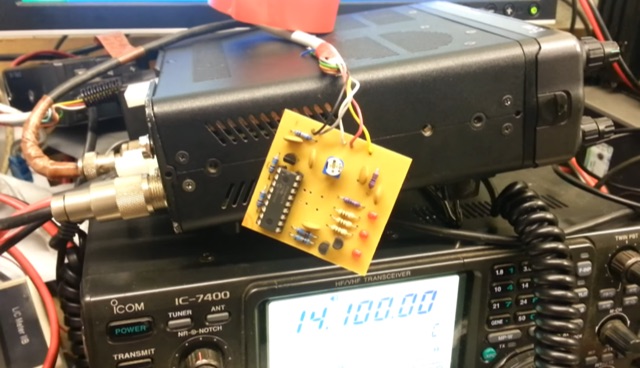 This project details an automatic roger beep circuit for VHF/UHF contests. Built around a Microchip PIC microcontroller, the design detects PTT (Push-To-Talk) activation and generates a brief tone upon release, mimicking a "roger beep" to signal the end of transmission. The circuit utilizes readily available components and includes downloadable resources for PCB layout and firmware.
 -
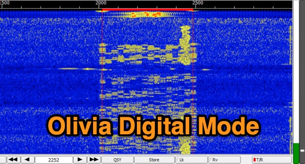 The Olivia digital mode, a **Multi-Frequency Shift Keying (MFSK)** radioteletype protocol, is specifically engineered for robust communication under difficult propagation conditions on shortwave radio bands from 3 MHz to 30 MHz. Developed by Pawel Jalocha in 2003, Olivia signals can be decoded even when the noise amplitude exceeds the digital signal by over ten times, making it highly effective for transmitting ASCII characters across noisy channels with significant fading and propagation phasing. Early on-the-air tests by Fred OH/DK4ZC and Les VK2DSG on the Europe-Australia 20-meter path demonstrated intercontinental contacts with as little as one-watt RF power under favorable conditions. Common Olivia modes are designated as X/Y, where X represents the number of tones and Y is the bandwidth in Hertz, with examples including 8/250, 16/500, and 32/1000. The resource clarifies that Olivia, unlike some other digital modes, produces a constant envelope, allowing RF power amplifiers to achieve greater conversion efficiencies and making it less prone to non-linearity. Operators are advised that **Automatic Level Control (ALC)** can be set higher than no meter movement for MFSK modulation, as long as it's not driven past its high limit, contrary to common misinformation about other digital modes. The Olivia community encourages voluntary channelization on suggested calling frequencies, such as 14.0725 MHz for 8/250, to facilitate initial contacts, especially for signals below the noise floor. The Olivia Digital DXers Club provides links to Groups.io, Facebook, and Discord for community engagement and offers details on QSO parties.
 -
 This project involved designing a 7-pole Chebychev broadcast band filter to address severe interference issues caused by a new horizontal loop antenna on the KN-Q7A transceiver. The interference overwhelmed the transceiver’s front end, so a custom filter with a 3.5 MHz cutoff was built using silver mica capacitors and type 6 T130 toroidal cores. Encased in a diecast box with SO239 sockets, the filter blocks strong signals from the broadcast band, achieving over 100 dB attenuation. Tested up to 100W, it reduces interference effectively while maintaining low insertion loss across HF bands.
 -
 An FT-817 ceased transmission on the VHF 2m band, despite the other HF, UHF, and 50 MHz bands operating correctly. Suspecting an excess of input signal during FT-8 mode transmission, they conducted measurements with an oscilloscope, revealing a burnt-out PIN diode, identified as D3003, type HSU277, on the PA unit board. Following the replacement of this surface-mounted diode, their FT-817 resumed operation on the 144 MHz band.
 -
 Operating amateur radio repeaters involves understanding frequency offsets, CTCSS tones, and the basic signal flow through a repeater system. This resource details the fundamental concepts of repeater operation, including the distinction between input and output frequencies, the role of **CTCSS (Continuous Tone-Coded Squelch System)** for access, and the typical frequency bands utilized for local communication. It clarifies terms such as "simplex" versus "duplex" operation and provides a diagram illustrating the signal path from a handheld transceiver to a repeater and back to another station, emphasizing the range extension repeaters offer. The article further explains practical aspects like identifying a repeater's offset (e.g., +600 kHz for 2-meter band) and the necessity of programming the correct tone. It compares the operational benefits of using repeaters for local communication over direct simplex contacts, highlighting how repeaters overcome line-of-sight limitations. The content is structured to assist new licensees in confidently making their first repeater contacts, providing a foundational understanding of how these critical infrastructure components facilitate wider area coverage for VHF/UHF amateur radio.
 -
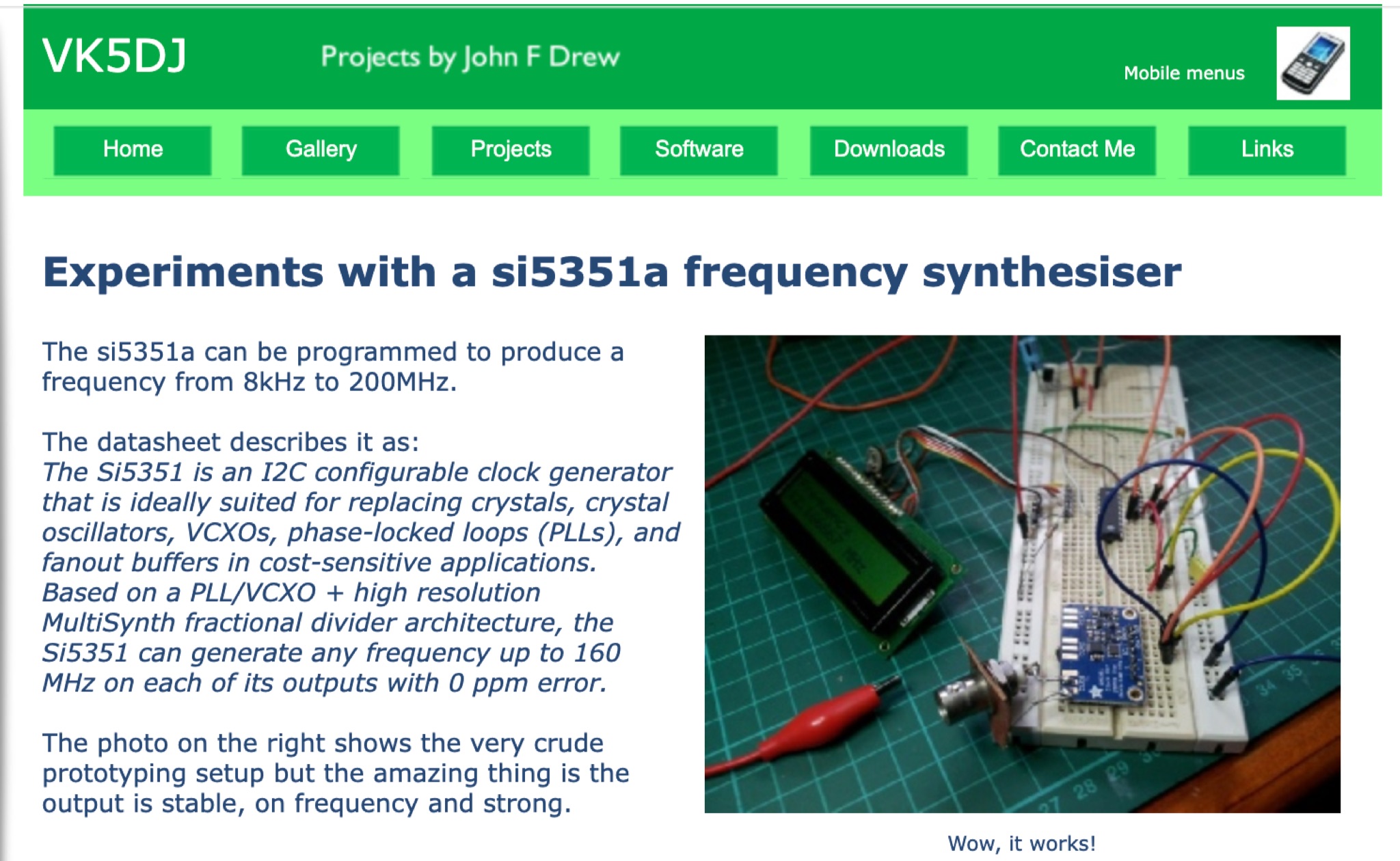 Explore VK5DJ's experiments with the si5351a frequency synthesizer, a versatile device capable of generating frequencies from 8kHz to 200MHz. Learn how this I2C configurable clock generator can replace crystals and oscillators in various applications, providing stable and precise outputs. Discover how to program the si5351a for your own signal generator projects and repeater site setups. Utilize the affordable and efficient Adafruit module for reliable performance. Enhance your understanding of PLL/VCXO architectures and fractional dividers for frequency generation. Join the PDS Forum community in experimenting with this innovative technology.
 -
 This **PDF report** documents a _maritime mobile_ DXpedition operating from the _Southern Ocean_ near Antarctica, detailing antenna deployment strategies on a sailing vessel. It addresses power management systems for remote operations and propagation characteristics specific to polar regions on **20m and 40m** bands. Operational strategies include managing high-density pileups using split frequency operation and maintaining signal integrity during periods of high aurora activity. Equipment considerations cover specific transceiver models like the Icom IC-7300, antenna types optimized for marine vessel installation, and battery power systems for extended periods without shore power. The resource also examines the use of satellite communication for real-time log uploads and QSL confirmation from remote locations, and discusses mitigating signal degradation from ice accumulation on antennas. DXZone Focus: PDF report | Maritime Mobile DXpedition | Polar Propagation | Split Frequency Operation
 -
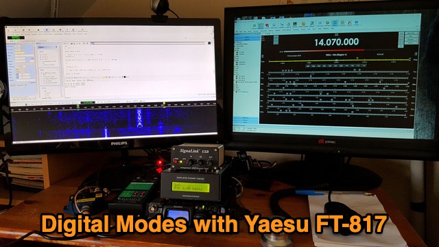 Setting up the Yaesu FT-817 and Signalink for data mode communication. Hardware and software required for data mode communication, connect and configure FT-817 and Signalink
 -
 This article will introduce total beginners to Amateur Radio, more commonly known as ham radio or DXing. That includes the basic definition - what DX is, where it came from, and the couple primary types (passive and active DXing). A Very Historical Past Radio Home!! The different kinds of DXing are well separated, indicating that you are either just listening to more distant stations, or engaging in a direct communication with another amateur. Ham Radio DXers: Importance of the Internet While the article glosses over the technical aspects of Ham radio equipment much like several of his articles, it does touch on how important the internet is to DXers. These include link to locate active stations, learn signal proagation, and be a part of the Ham community online.
 -
 Ham radio communication in the VHF and UHF bands, which was previously dominated by analog Frequency Modulation (FM), is increasingly incorporating Digital Voice (DV) modes. DV transceivers digitize audio and offer benefits like as signal integrity, encoded caller ID, and bandwidth savings. Today D-STAR, DMR and Yaesu System Fusion (YSF) are popular DV formats, each with its own set of features but mainly incompatible with the others. Internet access with Voice Over Internet Protocol (VoIP) expands DV communication worldwide. Repeaters and personal hotspots expand DV capabilities, enabling seamless worldwide connections. However, implementing DV frequently necessitates learning new technologies and negotiating network complexity.
 -
 The RXC70/10 is a sensitive 70 MHz to 10-meterband converter using the Philips SA602 mixer IC. It operates with high stability and low noise, converting 70–72 MHz signals to 28–30 MHz for general coverage receivers. The compact, low-power design (15mA) supports various modulations and uses. Its versatility makes it suitable for amateur radio applications with proper tuning and antenna setup.
 -
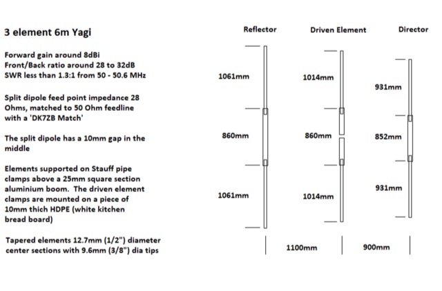 A small Yagi antenna for camper van. It is made of aluminum tubing, breaks down for storage, and works well for communicating with others. He built it in an afternoon and it gets good signal. The antenna is lightweight and can be packed up to fit inside his van while traveling
 -
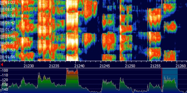 This article investigates SSB signal quality during the CQ WW 2015 SSB contest. It highlights the importance of adhering to the ideal SSB signal profile, the impacts of intermodulation distortion, and the consequences of poor-quality signals. The analysis underscores the need for well-tuned equipment to ensure cleaner, more efficient signals and, consequently, a more enjoyable and spacious experience for contest participants and amateur radio operators.
 -
 Amateur Television (ATV) is a ham radio technology that transmits and receives broadcast-quality video and audio. It utilizes existing standards for commercial television and can be used for various purposes including experimentation, entertainment, and public service events. ATV signals can be relayed over long distances using repeaters and are capable of transmitting live video from locations like the International Space Station. The article explores how to get started with ATV, highlighting its ease of use and suitability for beginners in ham radio. The future of ATV appears promising with advancements in digital and narrowband transmission techniques.
 -
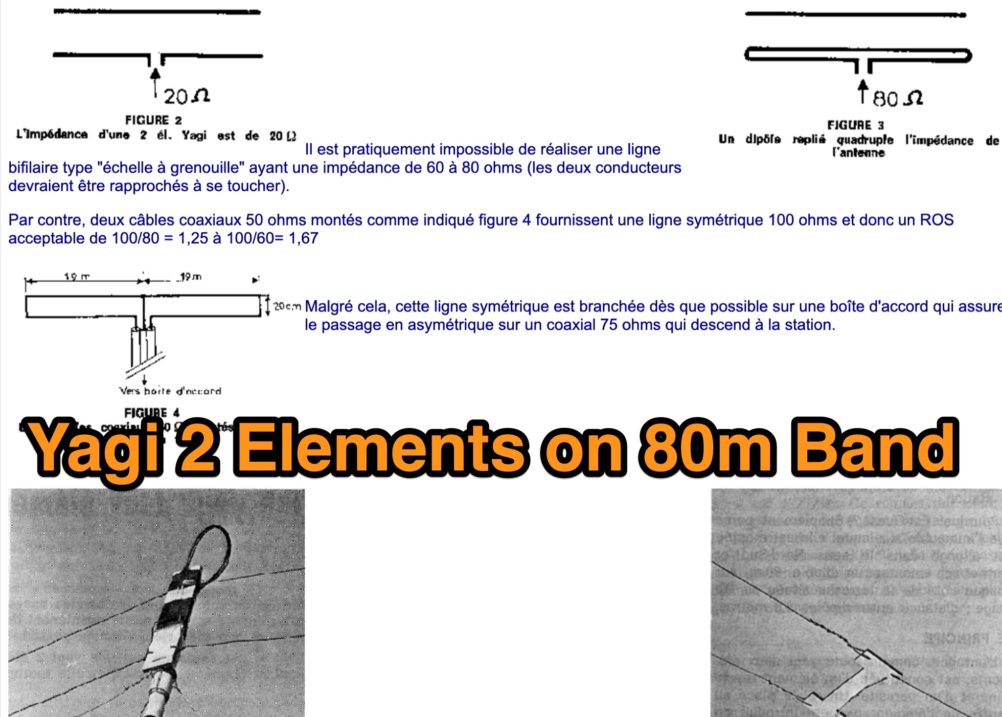 This article from the July 1976 issue of Radio REF discusses the trend of large antennas for ham radio operators on the low bands. It specifically focuses on a Yagi 2 element antenna for the 80m band, detailing its construction and functionality. The author explains how the antenna can be switched between directing signals towards the West or East using a switch at the station. The article also provides technical details on the lengths of the director and reflector elements, and how they impact the antenna's performance. A useful resource for hams looking to build or understand Yagi antennas for the 80m band.