Search results
Query: build an antenna
Links: 496 | Categories: 51
Categories
- Antennas > 20M > 20 meter Dipole Antennas
- Antennas > 20M > 20 meter Yagi antennas
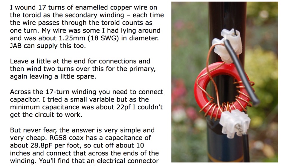
- Antennas > 40M > 40 meter Magnetic Loop Antennas
- Antennas > 6M > 6 meter Moxon Antennas
- Manufacturers > Antenna Parts
- Shopping and Services > Antenna Parts
- Technical Reference > Antenna Rotator
- Technical Reference > Antenna Switch
- Antennas > 160M
- Antennas > 6M
- Manufacturers > Antenna Parts > Aluminium Tubing
- Antennas > Capacitive
- Antennas > Feed Lines > Choke
- Antennas > CobWebb
- Antennas > Delta loop
- Software > Developer Resources
- Antennas > EH
- Antennas > End-Fed
- Manufacturers > Antenna Parts > Fiberglass tubing
- Antennas > G5RV
- Antennas > Halo
- Antennas > HB9CV
- Antennas > HexBeam
- Antennas > Homebrewing Techniques
- Antennas > Horn
- Antennas > Lindenblad
- Antennas > Microwave
- Antennas > Mobile
- Antennas > Moxon
- Antennas > Patch
-
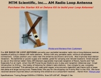 Loop Antenna Starter Kit contains detailed plans for building the MTM Scientific, Inc. loop antenna from scratch.
 -
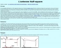 This doubet antenna is a half wave dipole antenna easy to build, in french
 -
 Presents the design and construction of the OK2FJ Bigatas, a portable, automatically tuned vertical antenna covering 80 through 10 meters. It details two distinct control systems: one utilizing BCD band data from Yaesu FT-857/897 transceivers, and another employing voltage level sensing for the Yaesu FT-817. The resource provides specific instructions for building the antenna's radiating element, loading coil with switchable taps, and the control circuitry, emphasizing the use of readily available components. The article outlines the physical construction of the antenna, including the use of duralumin tubes for the radiator and a PVC tube for the coil form. It specifies coil winding details, tap points, and the integration of radial wires for ground plane operation. The control electronics section provides schematics and component lists for both the BCD decoder (using a 74LS42 IC) and the voltage comparator (using an _LM3914_ bargraph driver), enabling rapid, automatic band switching without the minute-long tuning delays common in other systems. Crucially, the antenna achieves rapid band changes, with typical SWR values centered on common operating segments, such as **3.7 MHz** for 80m SSB. It also discusses modifications for CW operation on 80m and the trade-offs between antenna efficiency and full-range automatic tuning on higher HF bands, where manual adjustment of radiator length is suggested for optimal performance on 15m, 12m, and 10m. The resource includes construction photos and a discussion of cable requirements for reliable operation.
 -
 Presented here is a high-performance, circularly polarized omni-directional antenna that is easy to build, easy to tune, inexpensive, and will work all the mode J Low Earth Orbit (LEO) satellites
 -
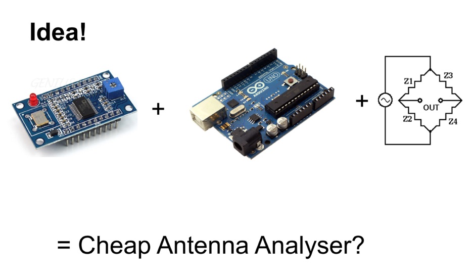 Build your own home made Antenna Analyzer with an arduino micro, or a cheeper one with a pic processor
 -
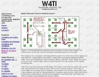 Remote Control Antenna Switch made with two circuits board
 -
 Build yourself a postage stamp 40 meter wire dipole antenna that fits in a space a little over 20 wide and works reasonably well at low heights
 -
 Ham Radio 20 / 40 meter short Coax Trap dipole antenna designed with the coax trap design calculator program
 -
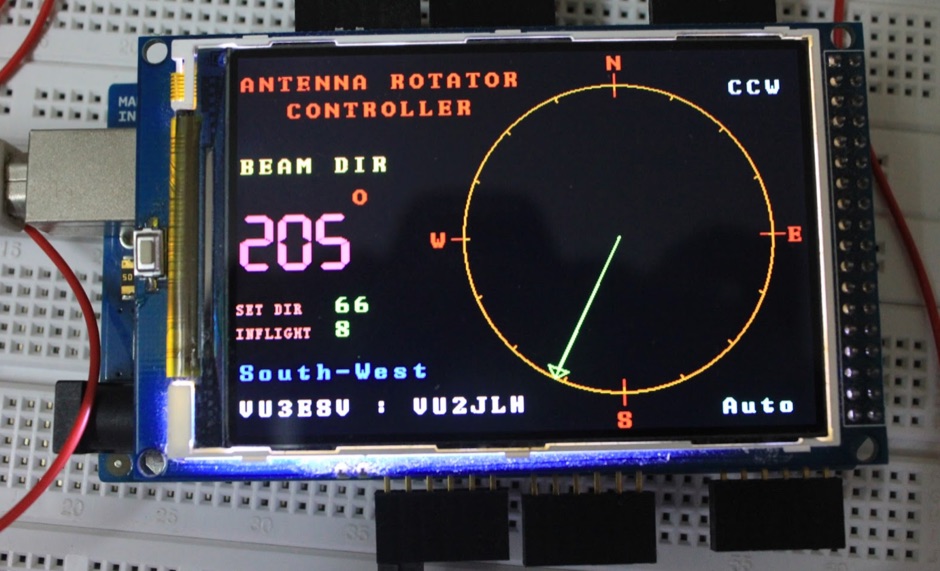 This is an attempt to build an Antenna rotator controller using Arduino Mega 2560 with a nice user interface showing the actual position of the antenna.
 -
 Presents a comprehensive guide for constructing a broadband Hex Beam antenna, a popular directional array for HF operation. This design offers a compact footprint and excellent gain characteristics, making it suitable for limited space installations while providing significant performance advantages over omnidirectional antennas. The resource details the specific dimensions for a five-band Hex Beam covering 20, 17, 15, 12, 10, and 6 meters, emphasizing the critical element spacing and wire lengths required for proper resonance and pattern. It outlines the construction of the center post, spreaders, and wire elements, along with the feed point assembly, ensuring proper impedance matching. The project aims for a forward gain of approximately **5.5 dBi** on most bands, with a front-to-back ratio often exceeding _20 dB_. Building this antenna requires careful measurement and assembly, but the resulting performance provides a substantial upgrade for DXing and contesting.
 -
 Hexagonal wire beams for all hf bands, technical resource, EZNEC files, tools for antenna modeling and documentation. You can also order parts to build your own antenna.
 -
 By ON4CFC Pascal, describe how to build a Sperrtopf or Sleeve antenna for the 144 Mhz, PDF File by antennex
 -
 The concept of the "Hula Loop" came after many years of building medium wave loops of varying size, shape and performance. Usually these loops are constructed on a square wooden frame, with wire being wrapped around the periphery
 -
 A 2.4 GHz WiFi antenna that can boost your WiFi signals for many miles. It\'s an easy to build Yagi antenna project done with some popsicle sticks, paper clips and glue.
 -
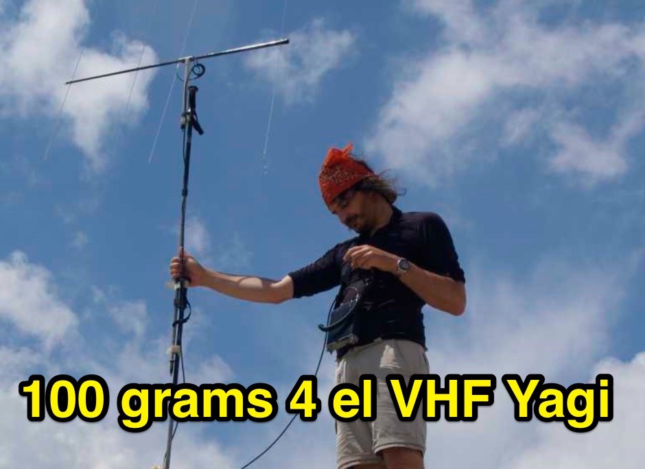 A portable VHF home-made Yagi-Uda antenna, that is extremely easy to build and very cheap. Moreover this antenna, while dismounted is just 1 meter long, and the total weight is just 100 grams.
 -
 A schematic design of the W3DZZ antenna in portugues with description of trap building
 -
 D3+ High Performance Antennas for Field Day. This article describes versatile broadband wire antennas. These antennas will double your effective radiated power over a dipole, will be easy and inexpensive to build and install, and will be simple to match.
 -
 An easy to build single wire antenna for 160 and 80 meters with a better than 2 to 1 swr across the 80 meter band
 -
 The Q-signal **QRP** signifies a request to reduce power, and in amateur radio, it defines operating with 5 watts or less for CW and 10 watts or less for SSB. This article addresses common inquiries from new hams regarding the practice, its benefits, and implementation methods. It explains how a 5-watt QRP signal, compared to a 100-watt signal, typically results in only a 13dB drop in signal strength, equating to about two S-units, still providing solid copy under most conditions. Hams choose QRP for various reasons, including seeking a greater challenge in DXing or contesting, reducing band interference, or enabling portable field operations with lightweight, battery-efficient equipment. A modern single-band CW transceiver, key, and antenna can fit into a pocket, offering receiver performance comparable to commercial rigs and extended operation on a small battery. This portability facilitates operations in remote locations where higher-power setups are impractical. Operating QRP can involve simply reducing power on an existing commercial HF rig or building a dedicated QRP transceiver from a kit, such as the **Wilderness Radio SST** with its 2-watt output and 15mA receive current draw. While SSB is viable, CW remains the most popular and efficient mode for QRP due to its superior signal-to-noise ratio. The article lists common QRP calling frequencies across 160m through 10m bands for both CW and SSB, and highlights organizations like QRP ARCI and NorCal that support the QRP community.
 -
 A wire yagi antenna model, easy to build, made using inverted vee elements and requiring just one support by ve3vn
 -
 An interesting article about co-linear or collinear antenna building, by Karl Shoemaker, AK2O
 -
 Multiband no trap no gap antenna. This Antenna is a small wonder, easy to build and allow you to work all HF spectrum with your TRX and it's internal ATU.
 -
 The AMRAD Active LF Antenna. You can tune into LF activity with this easy-tobuild and erect active antenna. As a bonus, you get MF and HF coverage, to not to mention world-class performance
 -
 Presents the detailed construction of the _FLA25HV_ antenna, a specialized array optimized for Earth-Moon-Earth (EME) communications on the 2-meter band. This resource provides schematics and practical insights into building a high-gain antenna system capable of reflecting signals off the lunar surface, a challenging but rewarding aspect of amateur radio. It covers the mechanical and electrical considerations essential for achieving the precise pointing and signal strength required for successful moonbounce contacts, often yielding **20 dB** or more gain. Amateur radio operators pursuing EME operations require robust antenna systems and precise tracking capabilities. The FLA25HV design addresses these needs by focusing on element spacing, impedance matching, and structural integrity to withstand environmental factors while maintaining critical alignment for lunar reflections. Such systems are crucial for making contacts over distances exceeding **768,000 km**. This personal page serves as a practical guide for hams interested in constructing their own EME arrays, offering a glimpse into the technical dedication involved in pushing the boundaries of VHF/UHF propagation.
 -
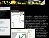
 Demonstrates the construction of two distinct wideband RF preamplifiers, detailing their component requirements and performance characteristics. The first design leverages monolithic microwave integrated circuits (MMICs) such as the MAR-6, MAR-8, or PGA103, offering a broad frequency response from DC to 2 GHz with a gain of 22.5 dB at 100 MHz and a noise figure typically below 3 dB. This MMIC-based amplifier incorporates protection against power supply transients and features a 50 Ohm input/output impedance, operating from an 8-20 volt supply with low current drain. The second preamplifier design utilizes a BSX-20 transistor, providing amplification across the 14 MHz to 550 MHz range. This simpler, more economical build achieves an average gain of 12 dB at 145 MHz and a noise figure of approximately 1.1 dB. It operates from a 7-15 volt battery supply with a current draw of 6 mA. Both projects emphasize critical construction techniques, such as maintaining short RF connections, ensuring 50 Ohm impedance paths, and mounting the circuit within a shielded enclosure to optimize performance and minimize noise. The resource also discusses phantom power options for antenna-mounted preamplifiers and precautions for use with transceivers, including output protection diodes and static bleeders.
 -
 An interesting article on building a 4 elements yagi antenna with gamma match for the 2 meter band. This article include two videos demonstrating assembling procedure by KG0ZZ
 -
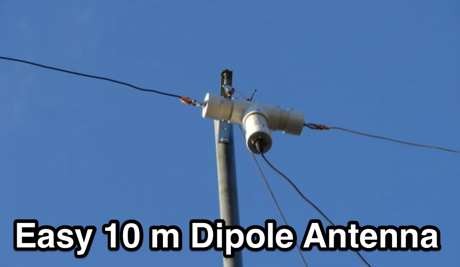
 A monoband end-fed half wave for 10m, 20m or any other HF band, includes a PDF with detailed information to build your own monoband or multiband antenna
 -

-
 40 meter vertical antenna construction, a shortened easy-to-build vertical, with no-radials, made from surplus military camouflage poles
 -
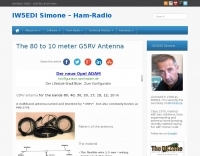 Yet another G5RV antenna plan to build a G5RV Antenna for 80 to 10 meters usage
 -
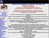 This project will enable you to build a monoband long wire inverted vee with 3/4 wave length sides that will have a bit of gain
 -
 A _Topfkreis_ antenna, also known as a "bicycle pump" antenna, is presented as a simple vertical design for the 70 cm band. This variant of the J-pole antenna is notable for not requiring a ground plane, simplifying deployment. The construction details specify using aluminum tubing for the radiating element, with precise measurements for the quarter-wavelength outer tube (32 mm diameter) and the three-quarter wavelength inner sliding tubes (10 mm and 8 mm). Feeding is via a 50-ohm coaxial cable connected 90 mm from the base of the central tube. This design can achieve a gain of **4 to 6 dB** when properly tuned using the adjustable radiating element. The article details the fabrication of a critical aluminum washer, suggesting a method using a hole saw and a drill press as a lathe for precise adjustment. The illustrated example is specifically for the 70-centimeter band, and the author, Pop, clarifies construction points in the comments, including material choices and assembly techniques, ensuring a robust build for VHF/UHF operation.
 -
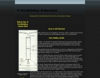 Cheap and EZ to build Bi-Directional VHF & HF antennas with gain
 -
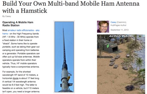 Build your own multi-band mobile ham antenna with a Hamstick
 -
 Presents a detailed construction guide for a **Quadrifilar Helix Antenna** (QHA) optimized for 137 MHz, specifically for receiving weather satellite transmissions. The resource outlines the author's experience building previous QHA designs, highlighting challenges with tuning and nulls, and then focuses on a refined design by John Boyer, documented by Steve Blackmore, which proved easier to build and yielded superior reception. The guide provides precise element dimensions, including 1.5m of 32mm PVC pipe for the mast and 8mm soft copper tubing for the helix elements. It specifies lengths for horizontal tubes (190mm, 90mm) and helix elements (903mm, 1002mm), along with instructions for drilling, assembly, and forming a **balun** by wrapping RG58 coax around the mast. The text emphasizes critical steps like ensuring elements are square and twisting in the correct direction to avoid phase issues. It includes references to original QST articles by Buck Ruperto (W3KH) and the WxSat program for decoding satellite transmissions, contextualizing the antenna's purpose. The article concludes with a sample NOAA 12 image from September 1998, demonstrating the antenna's reception capabilities.
 -
 This project is an attempt to build a portable standalone VNA (Vector Network Analyzer).
 -
 This resource details the conversion of an 80m elevated vertical antenna to include 160m operation, focusing on a relay-switched design over a trap-based approach. It presents specific feedpoint impedance values, such as **32 ohms** for 80m and **14 ohms** for 160m, and discusses the challenges of SWR drift encountered with the prior trap system during RTTY contesting. The article thoroughly explains the design choices for elevated radials, referencing _N6LF QEX data_ to debunk common myths regarding radial length and height, demonstrating that non-resonant radials can offer superior current uniformity. The construction section provides practical insights into building the vertical, including guying strategies, material selection from scrap pipe, and weatherproofing the relay assembly. It highlights the use of a common mode choke for the relay switching line, measuring approximately 5K ohms on both 160m and 80m, and details the L/C matching network's role in achieving a 50-ohm match at the end of a 300-foot RG-11 run. The author describes a precise VNA-based radial trimming procedure, achieving resonant values within a 3 KHz range. The content emphasizes the practical application of theoretical antenna principles, particularly concerning the interaction between the vertical element, cap hats, and the matching network. It offers a candid assessment of component selection, such as using junkbox parts and acknowledging the need for future upgrades to static drain resistors. The article serves as a comprehensive case study for advanced antenna builders tackling multi-band vertical designs.
 -
 Simple, easy to build, low cost, compact, multiband By Robert Wilson, AL7KK
 -
 Constructing a portable, high-gain antenna for _AO-40_ satellite operations presents unique challenges, particularly regarding mechanical stability and parabolic accuracy. This resource details the build of a 1.2-meter "brolly dish" antenna, utilizing a non-conducting fiberglass umbrella frame as its foundation. The project outlines a method for achieving a parabolic shape using stressed aluminum fly screen mesh, guided by practical geometry and a temporary dowel template. Key steps include selecting an appropriate umbrella with a suitable f/D ratio (ideally >0.25), removing the original fabric, and precisely cutting and attaching eight segments of fly screen to the struts to form the reflective surface. The construction process, which took approximately five hours for the author, _G6LVB_, resulted in a dish with an f/D of 0.27 (depth=270mm, diameter=1160mm, f=310mm). The article also describes a modification to a _TransSystem AIDC_ feed, incorporating a PCB reflector behind the dipole for easier mounting. Performance tests at a squint angle of 15 deg and a range of 50,000km yielded a signal-to-noise ratio of 33dB on the S2 beacon and 23dB for SSB signals, indicating strong reception. The author notes that the modified umbrella may not close fully without risking surface disfigurement.
 -
 How to homebrew a ENVIS antenna for 80 and 40 meters band
 -
 The ZS6BKW antenna, a popular multiband wire antenna, offers improved band matching compared to the traditional G5RV. This construction guide details the process, beginning with specific dimensions: 13.11 meters (43 feet) for the 450-ohm ladder line and initial dipole arm lengths of approximately 14.8 meters each. It emphasizes the critical role of an _antenna analyzer_ for accurate tuning, particularly for determining the velocity factor of the ladder line and achieving a 1:1 impedance match. The article outlines the materials required, including a 1:1 current balun, 450-ohm window line, wire for the dipole arms, and a 50-ohm non-inductive resistor for testing. It provides a step-by-step procedure for cutting the ladder line to its electrical half-wavelength, explaining how to calculate the velocity factor using measured and free-space frequencies. For instance, a measured 50-ohm impedance at 12.54 MHz with a calculated free-space half-wavelength frequency of 11.44 MHz yields a velocity factor of 0.91. Final adjustments involve hoisting the antenna to its operational height and fine-tuning the dipole arm lengths to achieve optimal SWR, specifically targeting 14.200 MHz. The _ZS6BKW_ design is noted for its performance on 80m, 40m, 20m, 10m, and 6m, though it is not optimized for 15m operation. The author, _VK4MDX_, shares practical tips for durable construction using stainless steel wire and cable clamps.
 -
 Presents the design and performance of a 4-element wire Yagi antenna for the 40-meter band, building upon VE3VN's earlier 3-element switchable wire Yagi. The resource details the antenna's evolution, highlighting the transition from a 3-element to a 4-element configuration and the resulting improvements in gain and front-to-back ratio. It provides specific insights into the antenna's construction and expected operational characteristics. VE3VN shares insights from field results, noting the antenna's performance on 40 meters. The discussion includes the antenna's pattern and matching characteristics, crucial for any DXer or contester looking to optimize their signal on this popular HF band. The author's experience with the previous 3-element design informs the enhancements made to this 4-element iteration. The article includes a visual representation of the antenna's current view, offering a practical perspective on its physical layout. It serves as a valuable reference for hams considering a directional wire antenna for 7 MHz operations, demonstrating a practical approach to achieving enhanced directivity and gain.
 -
 An home made SWR meter for 2.4 GHz. A DIY SWR meter that allow precise measurements and calibration of any WiFi antenna. This is test equipment everyone who build wifi antennas should have in their shack. Article is in french and include some videos.
 -
-
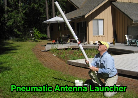 How to build the Quickie Pneumatic Antenna Launcher
 -
 Calculate EH Antenna, 20m 40 80m. Fotos, Original eh antenna building.
 -
 Homebrew a cobwebb antenna for the HF bands. This page describe a cobwebb multiband antenna resonating on 14 18 21 24 and 28 MHz. The cobweb antenna model can be considered a fan dipole, or better, multiple dipoles fed in parallel.
 -
 A balun is a MUST for dipoles or similar antennas when they are feed with coaxial cables. Many hams connect the center conductor of the coaxial cable to one side of the dipole, and the shield to the other. Wrong!
 -
 How to build your own beverage antenna for 80-160 meters band by K5ZD
 -
 This article describes a project of asymmetrical hatted vertical dipole, a portable antenna that can be used for field day operations, sota, campings or even for fixed installations. This is a freestanding 20-10m antenna that is really easy to build, easy to tune and relatively easy to carry.