Search results
Query: ari
Links: 622 | Categories: 208
This query is too generic. Please try adding an additional term to focus your research.
Categories
- Ham Radio > Clubs > North America > USA > Arizona
- Software > Grid Bearing and Maps
- Antennas > Maria Maluca
- Manufacturers > Antennas > Marine
- Shopping and Services > Marine Radio
- Radio Scanning > Maritime
- Operating Modes > Mobile > Maritime Mobile
- Ham Radio > Clubs > North America > Canada > Ontario
- Operating Aids > Distance & Bearing
- Radio Equipment > Reviews and Comparisons
- Antennas > Baluns > 1 to 1 Balun
- Antennas > 15M
- Antennas > 20M > 20 meter Yagi antennas
- DX Resources > DX Peditions > 2010 DXpeditions
- DX Resources > DX Peditions > 2012 DXpeditions
- DX Resources > DX Peditions > 2013 DXpeditions
- DX Resources > DX Peditions > 2017 DXpeditions
- DX Resources > DX Peditions > 2021 DXpeditions
- Antennas > 20M
- Antennas > 23cm
- Antennas > Baluns > 4 to 1 balun
- Antennas > 40M > 40 meter Loop Antennas
- Antennas > 40M
- Antennas > 6M > 6 meter Yagi Antennas
- Antennas > 70cm
- Radio Equipment > HF Amplifiers > Alpha 9500
- Radio Equipment > Amateur Radio Accessories
- Radio Equipment > HF Amplifiers > Ameritron ALS-600
- Software > Antenna analysis
- Manufacturers > Antenna Analyzers
-
 Presents the mechanical and electrical specifications for a 5-element Yagi beam antenna designed for the 6-meter band. The resource details element lengths, spacing, and boom dimensions, specifically utilizing _EMT conduit_ for construction. It includes a diagram illustrating the element layout, a coaxial balun connection, and a reported SWR curve, providing a practical blueprint for hams to replicate the design. The design achieves a reported SWR of **1.1:1** at 50.125 MHz, indicating efficient impedance matching across the primary 6-meter DX window. The boom length is specified at 2.44 meters (8 feet), with element lengths ranging from 2.87 meters for the reflector to 2.59 meters for the director 3. This configuration suggests a gain figure typical for a 5-element Yagi, likely in the range of **9-10 dBi**, making it suitable for local and sporadic-E DX contacts.
 -
 This application note is designed to help the reader understand how balun transformers can be used in today's RF/Microwave communication applications.
 -
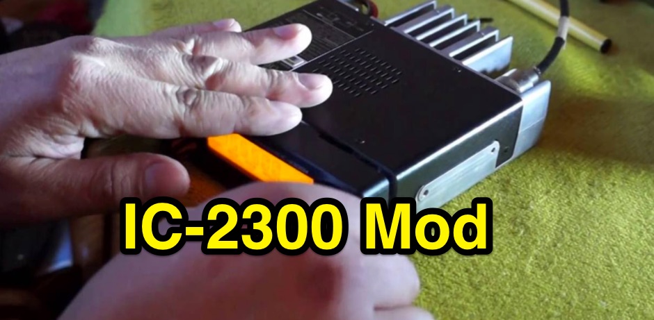 IC‐2300 MARS/CAP mod expanded frequency range 136‐174 MHz
 -
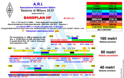 Ari Milano draw and keep updated these pdf files representing the "radioamatori" bandplan, with notes in italian
 -
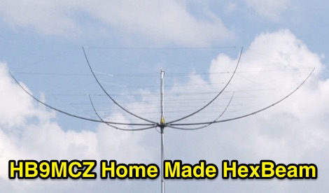 A project for a homemade multiband Hexbeam antenna for 10, 12, 15, 17 and 20 meters
 -
 The PDF document, titled "J-Poles," presents various J-pole antenna designs covering the 50 MHz to 450 MHz frequency range. It includes construction details for several specific bands, such as a 6-meter J-pole, a 2-meter J-pole, and a 70-centimeter J-pole. The content outlines the fundamental principles of J-pole operation, including the quarter-wave radiator and half-wave matching stub. Each design features specific dimensions for elements like the radiator length, stub length, and spacing, often expressed in inches. The document also discusses feeding arrangements and impedance matching considerations inherent to J-pole antennas. It provides practical guidance for homebrewing these antennas using common materials like copper pipe or wire elements. The resource offers insights into the advantages of J-poles, such as their omnidirectional pattern and ease of construction, making it a practical reference for radio amateurs interested in VHF/UHF antenna projects.
 -
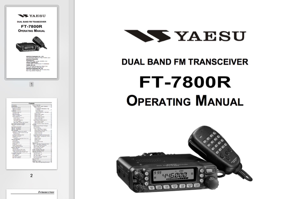 English version of the Yaesu FT-7800 operating manual
 -

-
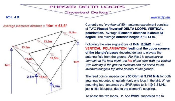 An interesting article with many technical details on a phased delta loop array for 80 meters band includes pictures of antenna relays
 -
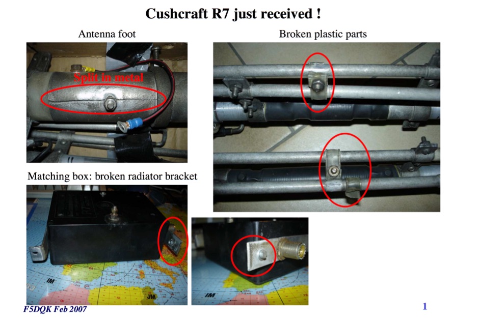 F5DQK repairing and swr measurement tests of a Cushcraft R7 Antenna
 -
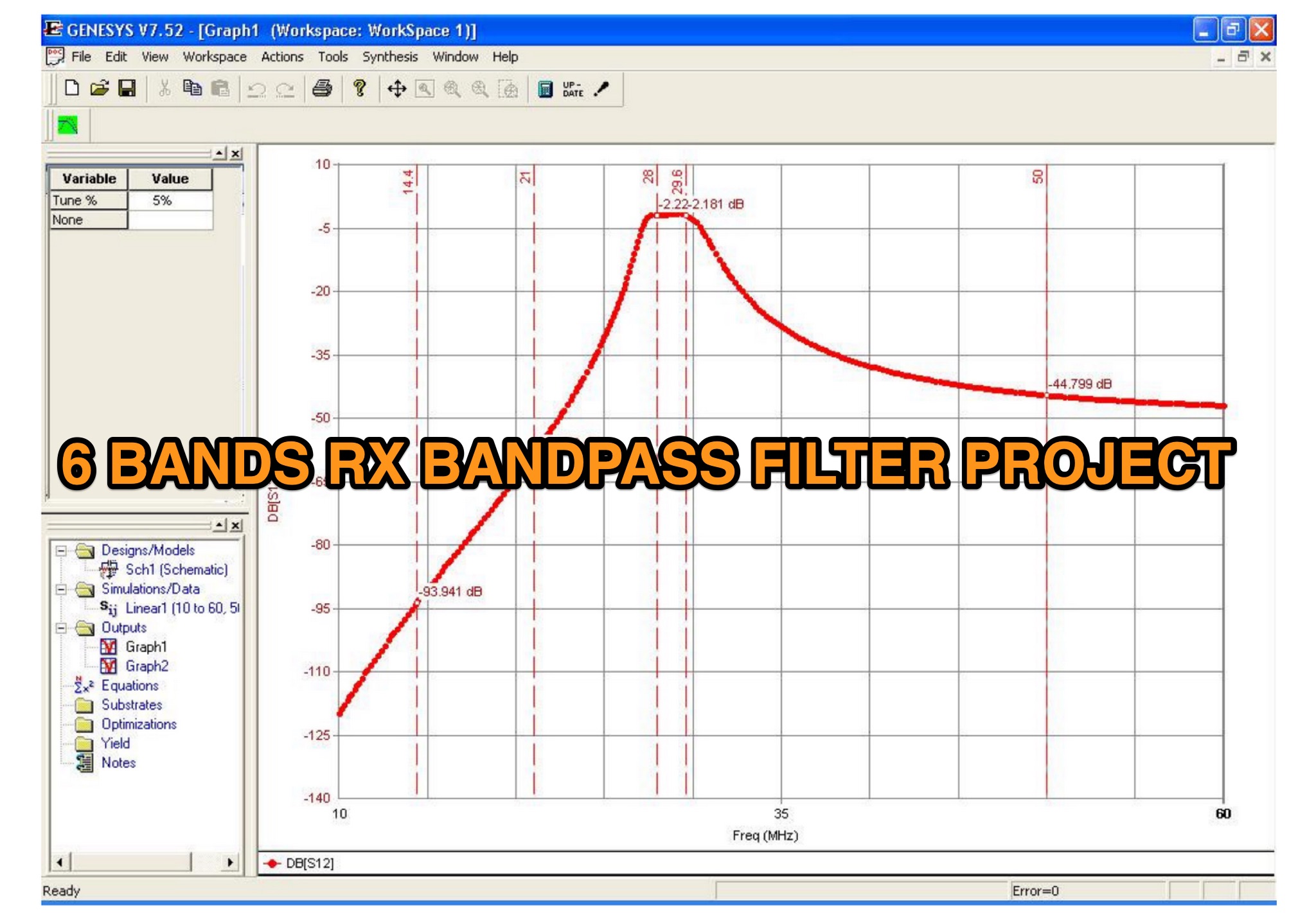 This is a 6 band receive only filter designed to protect your receiver front end and provide 45dB reject at the stop bands. This is a 6-band receive only filter designed to protect your receiver front end and provide 45dB reject at the stop bands. Stop band reject may be limited by the relay isolation. Worse case isolation is at 28 MHz or 35 dB or better. Relay K3/K8 protects the filter during transmit via the PTT line. A 25-50ms delay must be used between transmit and PTT. Do not rely on your radio to provide adequate delay with out using the PTT. You logging software must be set to allow a delay between PTT and time of 1st transmit. This filter will not work with VOX or QSK keying as you will damage the filter.
 -
 The problem with making your own trapped HF antennas is usually getting the coaxial traps tuned to frequency.
 -
 An antenna originally planned in the sixties, a two element beam antenna tunable on several band, in french
 -
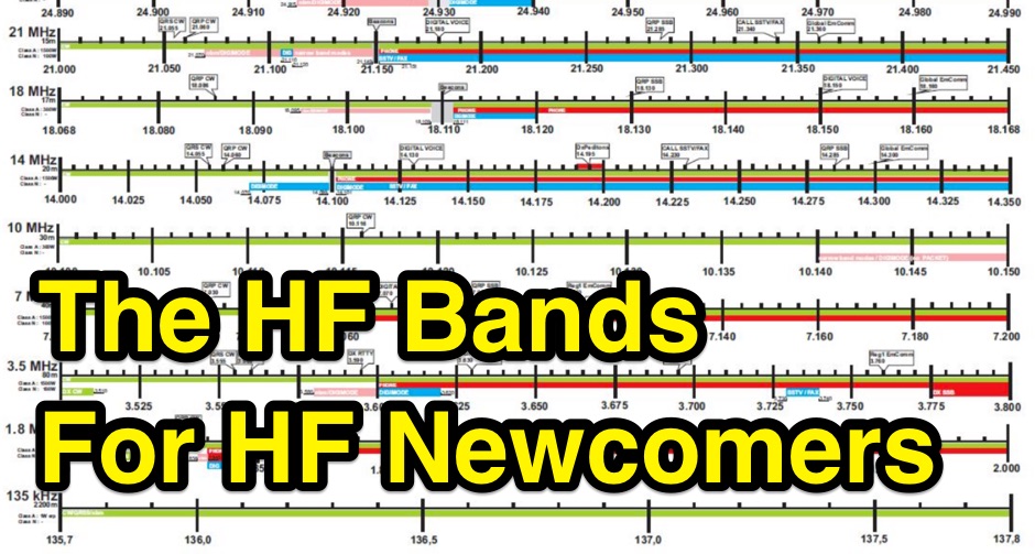 The HF ham bands can be mysterious. Some work at night, some during the day. Some seem to be good for long distance contacts while some are better for nearby contacts. Even worse, they change tremendously from hour to hour and day to day. An overview on operating on HF amateur radio bands
 -
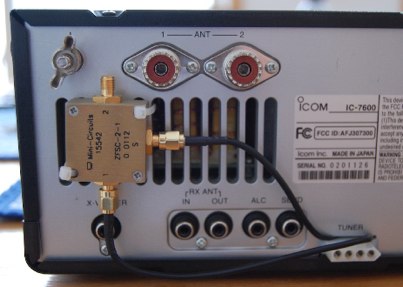 An easy mod to make the 1st IF of the Icom IC-7600 accessible and connect to a cheap RTL SDR dongle by VE4NSA
 -
 Constructing a portable, high-gain antenna for _AO-40_ satellite operations presents unique challenges, particularly regarding mechanical stability and parabolic accuracy. This resource details the build of a 1.2-meter "brolly dish" antenna, utilizing a non-conducting fiberglass umbrella frame as its foundation. The project outlines a method for achieving a parabolic shape using stressed aluminum fly screen mesh, guided by practical geometry and a temporary dowel template. Key steps include selecting an appropriate umbrella with a suitable f/D ratio (ideally >0.25), removing the original fabric, and precisely cutting and attaching eight segments of fly screen to the struts to form the reflective surface. The construction process, which took approximately five hours for the author, _G6LVB_, resulted in a dish with an f/D of 0.27 (depth=270mm, diameter=1160mm, f=310mm). The article also describes a modification to a _TransSystem AIDC_ feed, incorporating a PCB reflector behind the dipole for easier mounting. Performance tests at a squint angle of 15 deg and a range of 50,000km yielded a signal-to-noise ratio of 33dB on the S2 beacon and 23dB for SSB signals, indicating strong reception. The author notes that the modified umbrella may not close fully without risking surface disfigurement.
 -
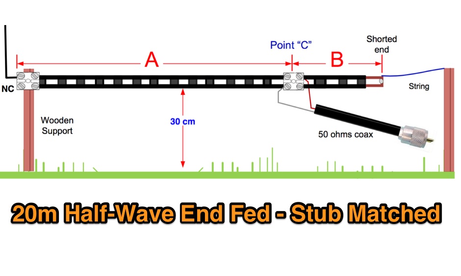 A Half wave antenna has a high impedance feed point. This can be matched using a 1/4 wave stub matching section and converts the 40m vertical into an L-shaped 20m J-Pole antenna. The 300 ohm feeder used for this purpose must be kept away from the ground.
 -
 Review by G3TXQ and comparison to its modificated versions. SWR Measurements on inverted V setup and comparison from EZNEC model and a real one.
 -
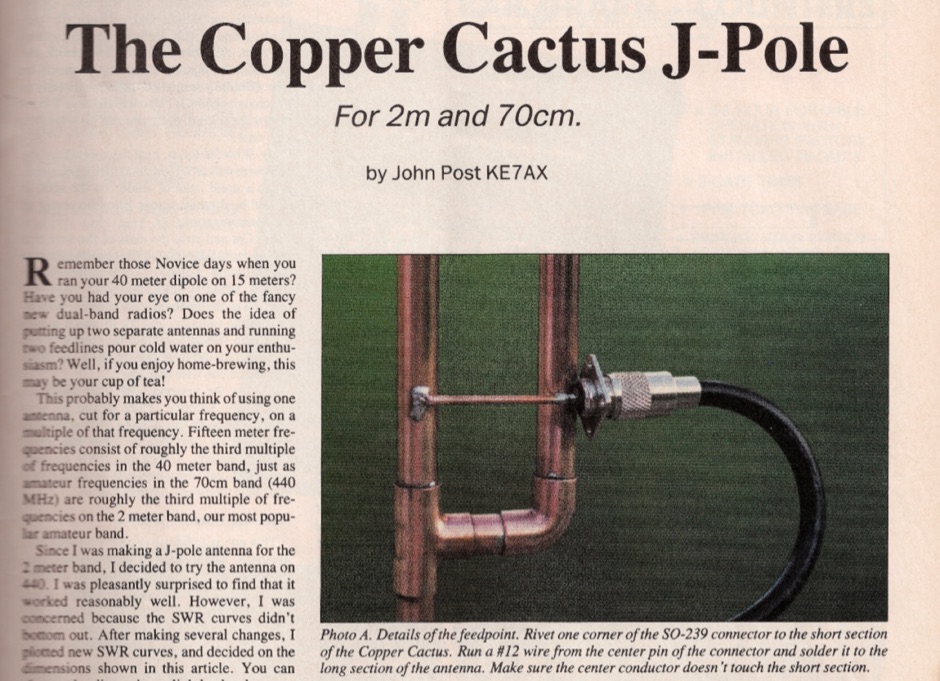 Original article published on February 1992 on 73 Amateur Radio Today about the 2m and 70 cm copper cactus J-pole antenna
 -
 Amateur Radio (G3TXQ) - Malta 40 QRP CW Transceiver
 -
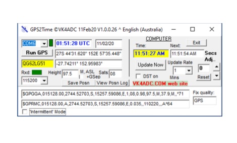 A means of sync-ing your computer clock using a GPS Receiver. GPS2Time is another GPS network time synchronization software application for Window 7 and higher. Freeware.
 -

-
 The resource details the construction of a 6-meter _Moxon_ antenna, presenting two distinct versions: one horizontally polarized for 50-51 MHz CW/SSB and another vertically polarized for 52-54 MHz FM. It specifies the use of 5/8 inch OD and 1/2 inch OD aluminum tubing, with 3/8 inch OD solid aluminum for corners, and provides a comprehensive material cutting schedule. The design aims for robust, portable construction, with all materials costing under $100. Detailed drawings and EZNEC models are referenced for precise dimensions and assembly, ensuring accurate element spacing and impedance matching. The EZNEC model for the H-POL version predicts a gain of **11 dBi** and a front-to-back ratio of **25 dB** at 50.5 MHz, while the V-POL version shows a gain of **6.7 dBi** and a front-to-back ratio of **36 dB** at 53 MHz. The article includes practical SWR measurement advice, noting the impact of coax length and loss on analyzer readings. Field tests during a tropical storm demonstrated the antenna's durability and performance, yielding numerous contacts across significant distances, including California, Colorado, and Texas, on SSB and PSK.
 -
 The Vee Beam antenna project presents a versatile solution for hams, enabling operation across all eight High Frequency bands (80m to 10m) with significant gain on 20m to 10m. This easy-to-construct antenna utilizes two long wires at an angle, enhancing directional performance and minimizing ground losses. With a low visual profile, it is discreet and effective for various applications. The design allows for optimal leg lengths and included angles, ensuring robust performance while maintaining simplicity in construction and operation. The V Beam antenna is an aerial that you can use on all eight High Frequency amateur bands (80, 40, 30, 20, 17, 15, 12 and 10m) with an antenna tuner, and which gives significant gain on the five bands from 20 to 10 meters band.
 -

-
 GW4ALG's _136 kHz Pages_ document the evolution of vertical antennas for the 2200m band, starting with a prototype mounted on a house wall. This initial design, despite achieving the first **395 km** GM-GW QSO, suffered from significant insulation breakdown, high RF losses due to proximity to the house, and difficult tuning adjustments. The author details the challenges of maintaining resonance and matching with a variometer in the loft, noting that adding three earth spikes offered no measurable improvement over a simple water tap connection. The subsequent experimental 12m vertical, relocated away from the house, significantly reduced dielectric losses and proved far more effective. This antenna enabled GW4ALG to set a world DX record on 136 kHz with a **1916 km** QSO to OH1TN, and an intra-UK record of **703 km** to GM3YXM/P. The resource further explores the use of helium-filled balloons to extend the vertical radiator, achieving heights up to 27m, typically 20m, for enhanced low-band performance. Practical advice on balloon types, inflation, and critical insulation between the wire and balloon is provided, emphasizing safety and avoiding arcing.
 -
 Official Icom comparison chart for IC 756 PRO III, IC-7600, IC-7700 and IC-7800
 -
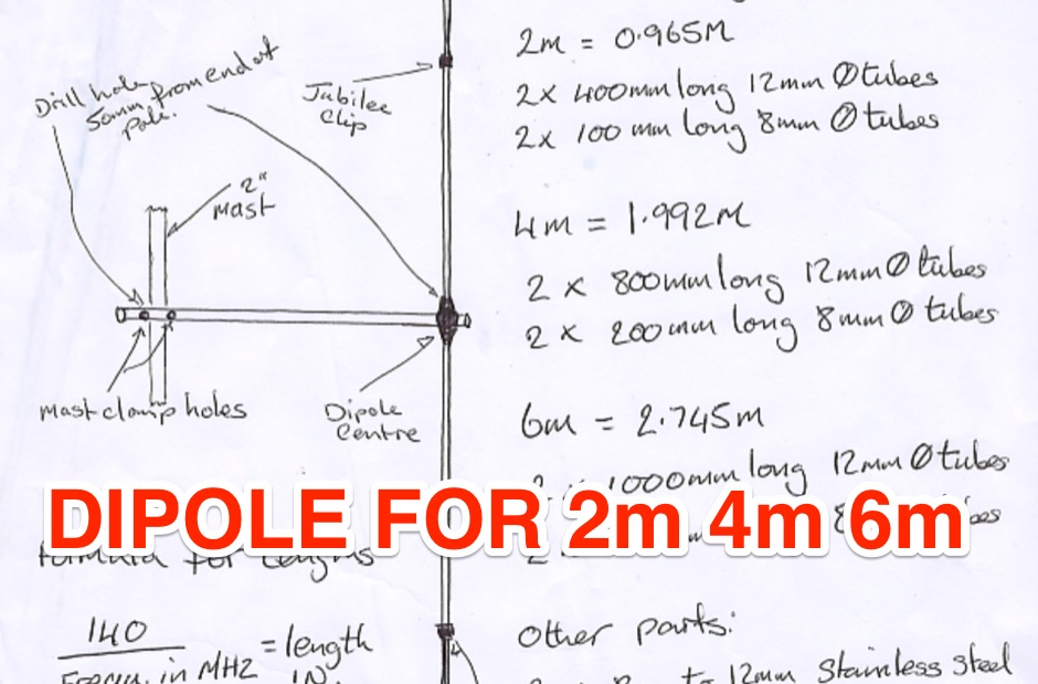 A dipole for 2m, 4m, 6m band an hamdwritten note for a homemade vhf antenna that can be tuned across the VHF band
 -
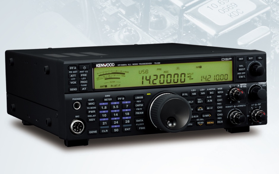 Step by step instructions for setting up N1MM Logger to communicate with the TS-590S using the USB connection
 -
 This article presents a technical investigation into spurious emissions from the Yaesu FT-847 transceiver when operating on the 70MHz (4-meter) band. The author discovered significant problems with both factory "UK spec" and modified units. Spectrum analysis revealed that when transmitting at 70.2MHz, the radio produces numerous spurious signals, with the most prominent emission at 45.6MHz measuring only 3dB below the fundamental frequency. The study also documents poor power efficiency on 4m (10.3% at 30W output) compared to 6m operation (23.5% at 30W). Tests verified that jumper configurations had no effect on filter selection. The author warns that using these radios on 4m may violate license conditions due to excessive spurious emissions.
 -

-
 Making your own 2 metre (146 MHz) 5/8th wave whip antenna
 -
-
 This program demodulates the telemetry data signal transmitted by the AO-40 satellite (aka Phase III-D) using the PC sound card
 -
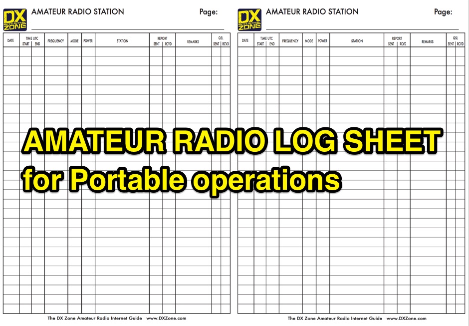 A free to download and print, paper log sheet useful for portable amateur radio operations, in a PDF file.
 -
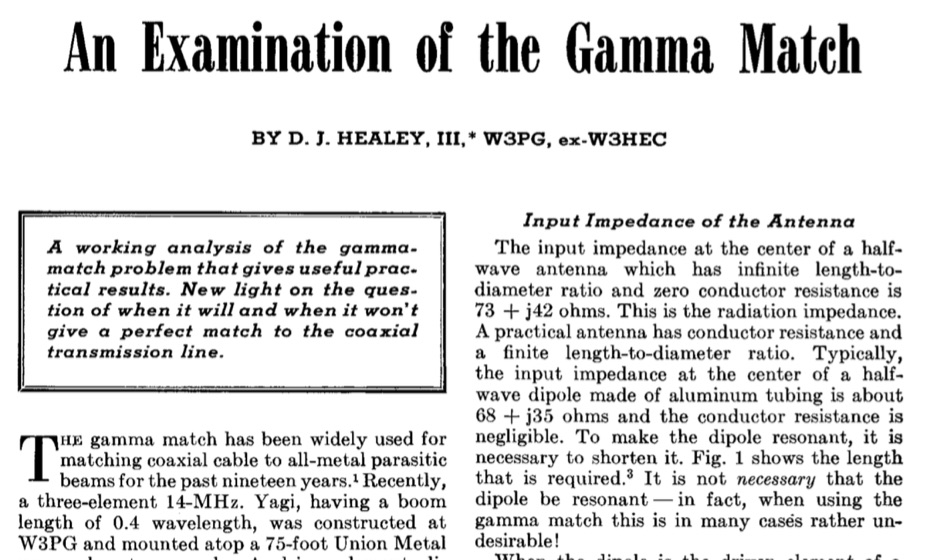 A Working analysis of the gamma match problem that gives useful practical results in a article dated April 1969.
 -
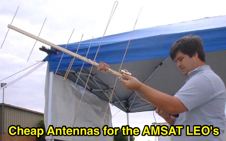 Cheap Antennas for the AMSAT LEO Kent Britain WA5VJB
 -
 Meimaris Communication Equipment based in Greece
 -
 Notes on Axial-Mode Helical Antennas in Amateur Service. Helix Basics, Modeling Issues, and Short Helical Antennas Over Perfect Ground
 -
 A DIY project details the construction of a modular QRP CW transceiver specifically designed for the **20-meter band**. The design is segmented into three distinct modules—VFO, Receiver, and Transmitter—allowing for phased construction and independent testing. The VFO circuit, capable of operating as a conversion VFO or a free oscillator, provides a frequency span of approximately _70 KHz_ (2.433 to 2.510 MHz) with a 4V pp output level, utilizing a Colpitts FET oscillator and buffer. The receiver employs a classic superheterodyne architecture with MOSFETs in the front end and mixer for improved overload immunity, incorporating a 4-crystal ladder filter with a 600 Hz bandpass and an LM386 audio power amplifier delivering about 1W into an 8-ohm load. The transmitter section uses frequency conversion with an NE602 mixer to achieve 14 MHz operation, featuring a power broadband stage capable of 4-5W output into a dummy load, and includes a double Pi filter for signal cleanliness. The resource provides detailed component lists, tuning instructions for each module, and 1:1 scale PCB layouts for single-sided boards.
 -
 ARRL affiliated organization
 -
 This simple modification is applicable to pretty much any 12 volt operated, positive earth equipment. by Chris Cox, N0UK, G4JEC
 -
 Comparison chart for low-band receiving antennas
 -
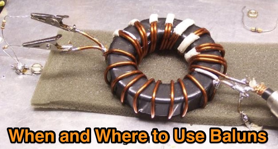 The document provides a comprehensive overview of baluns, which are devices used to connect balanced loads, like dipole antennas, to unbalanced inputs, such as coaxial cables. It covers various types of baluns, including voltage and current baluns, and their design, construction, and testing. The text discusses the importance of baluns in preventing RF currents on coax shields and their applications in Ham radio setups. It also includes practical advice on selecting and using baluns based on antenna impedance and power ratings, along with detailed performance evaluations and construction tips for different balun configurations.
 -
 This document details the design and construction of a Vinecom 6N4 dual-band Yagi antenna for the 50MHz (6-meter) and 70MHz (4-meter) amateur radio bands. The antenna features 9 total elements (4 elements for 50MHz, 5 elements for 70MHz) on a 4.236-meter aluminum boom. Computer simulations using MMANA software predict 7.21 dBd gain on both bands with front-to-back ratios of 16.01dB (6m) and 15.37dB (4m). The design uses 12.7mm diameter elements mounted on a 32mm square boom, weighing 5.7kg total. Practical measurements with an MFJ-269 analyzer confirmed good SWR performance across both bands after element length adjustments.
 -
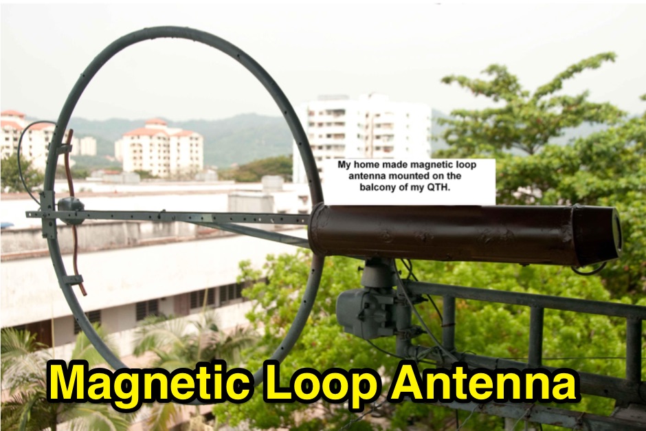 If you have space constraint at your QTH for a HF antenna, you can try contructing this HF magnetic loop antenna for 40-20 meters bands
 -
 Homebrew a compact yagi antenna for 14 Mhz suitable for those with small plots based on a design by AB4GX
 -
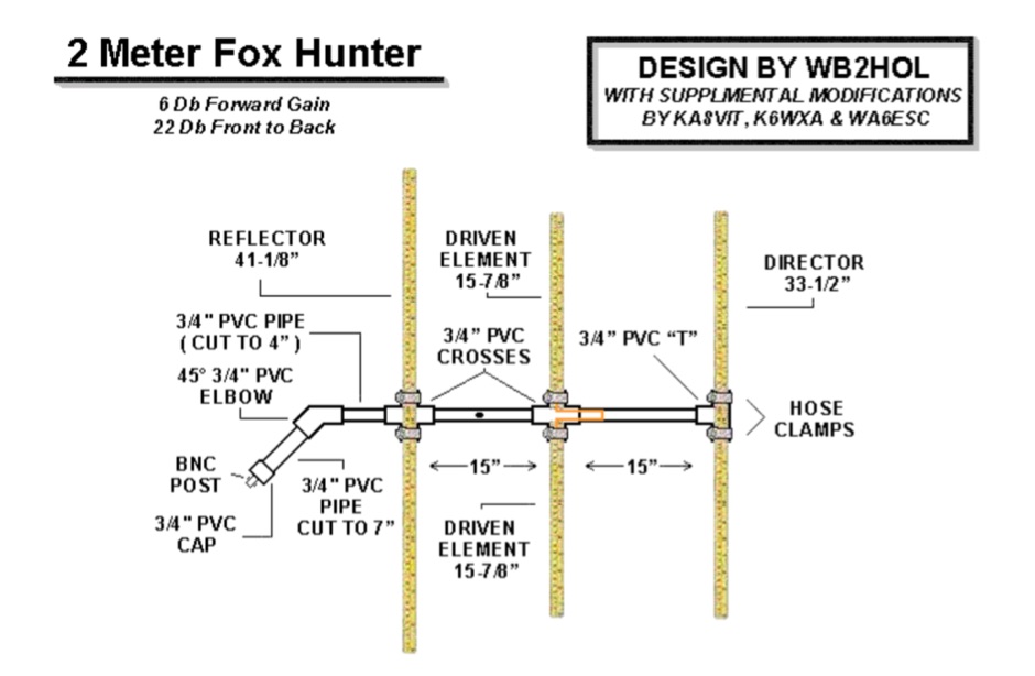 A home made yagi antenna featuring 6db forward gain and 22 Db front back
 -
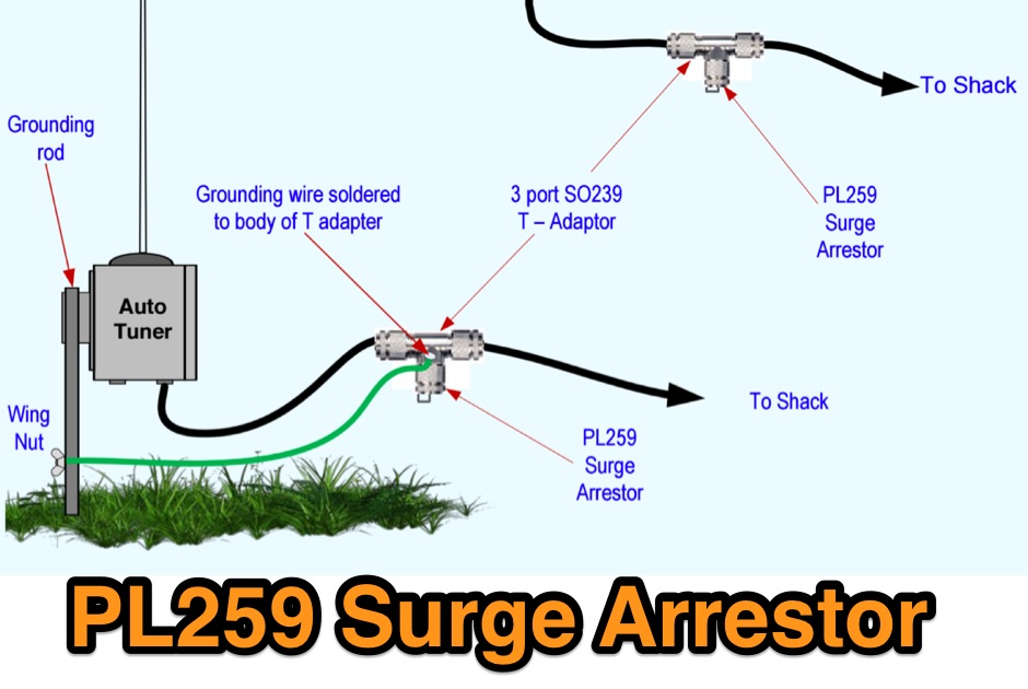 A sourge arrestor for PL 259 connectors. A voltage surge arrestor to limit the voltage that may come back down the wire or coax after there has been static build up
 -
 At the moment the most used program is UA1AAF. It is an excellent program written by Boris, UA1AAF, to handle ARI International DX Contest. It can simulate K1EA or N6TR workings; it will be possible to connect the RTX to the computer using a standard interface in such a way as to transmit directly in CW from the keyboard; most of the controls are like K1EA's CT and N6TR's TR ; on line help provides almost all the information necessary for using the program. Is possible to insert QSO after the contest. An appropriate utility in included for conversion in ADIF format. The program is very small and therefore works without any problems on any IBM compatible computer with DOS 3.3 and over or Windows 95/98.