Search results
Query: band
Links: 716 | Categories: 111
This query is too generic. Please try adding an additional term to focus your research.
Categories
- Ham Radio > Band Plans
- Antennas > Multiband
- Operating Modes > Top Band
- DX Resources > Beacons > 10 GHz Beacons
- DX Resources > Beacons > 10 meter beacons
- Antennas > 10M
- Antennas > 17M
- Antennas > 20M > 20 meter Dipole Antennas
- Antennas > 20M > 20 meter Vertical Antennas
- Antennas > 20M > 20 meter Yagi antennas
- Antennas > 20M
- Antennas > 23cm
- Antennas > 2M
- Antennas > 30M
- Antennas > 40M > 40 meter Dipole Antennas
- Antennas > 40M > 40 meter Loop Antennas
- Antennas > 40M > 40 meter Yagi Antennas
- Antennas > 4M
- Antennas > 6M > 6 meter J-Pole Antenna
- Antennas > 6M > 6 meter Moxon Antennas
- Antennas > 60M
- Operating Modes > 70 MHz
- Antennas > 80M
- Radio Scanning > Aeronautical
- Operating Modes > Aircraft scatter
- Radio Equipment > VHF-UHF Handhelds > Baofeng UV-3R
- Technical Reference > Beacon keyers
- Software > Beacon Monitoring
- DX Resources > Beacons
- Technical Reference > Radio Frequency Interference > BPL
-
 The document is a technical guide on designing RF filters for radio frequency applications. It covers topics such as interference suppression, band-pass filters, and low pass filters, with a focus on filter design and circuit filters.
 -
 Practical and usable direct conversion receiver for the 40 m CW band
 -
 This is a design for a stealthy HF multi-band vertical wire antenna using a tree as a supportby G7AQK
 -
 The G5RV multiband HF antenna, designed by Louis Varney (G5RV) in 1946, is a popular compromise antenna offering good overall performance on most HF bands when paired with an external antenna tuner. The basic full-size G5RV measures 102 feet across the top for 80 through 10 meter operation and is fed at the center via a 34-foot low-loss feed-stub. This interaction between the radiating section and the feed-stub facilitates matching across 80-10 meters with a standard tuner, often eliminating the need for ladder line directly to the shack. The antenna's design center frequency is 14.150 MHz, configured as a 3/2-wave dipole on 20 meters, with its 102-foot length derived from long-wire antenna formulas. Construction details emphasize the matching section, which can be open wire, ladder line (window-type), or TV twin lead. Each type has a specific velocity factor (VF) affecting its physical length for an electrical half-wave on 14 MHz; for instance, open wire requires 33.7 feet (VF 0.97), ladder line 31.3 feet (VF 0.90), and TV twin lead 28.5 feet (VF 0.82). The article provides formulas for calculating these lengths and discusses the antenna's behavior on individual bands, from 3.5 MHz where it acts as a shortened dipole, to 28 MHz where it functions as two three-half-wave long-wire antennas fed in-phase. Practical construction notes include recommendations for vertical descent of the matching section, sealing the coax junction, providing strain relief, and winding a coaxial choke coil to mitigate common mode current. The resource also presents dimensions for double-size (204 ft) and half-size (51 ft) G5RV versions, along with their corresponding matching section lengths for various line types, making it a versatile reference for hams considering this classic wire antenna.
 -
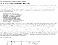
 Construction details of a multiband dipole that can can operate at high power levels, and match its 50-ohm coax feedline without a tuner
 -
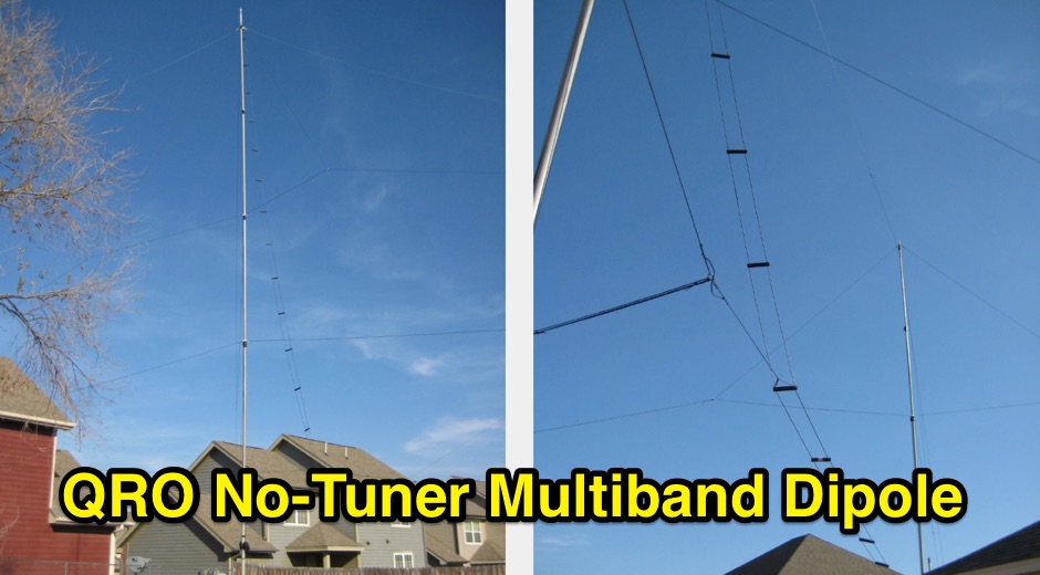
 An easy to make, cheap, no trap, multiband wire vertical antenna by PA1M
 -
-
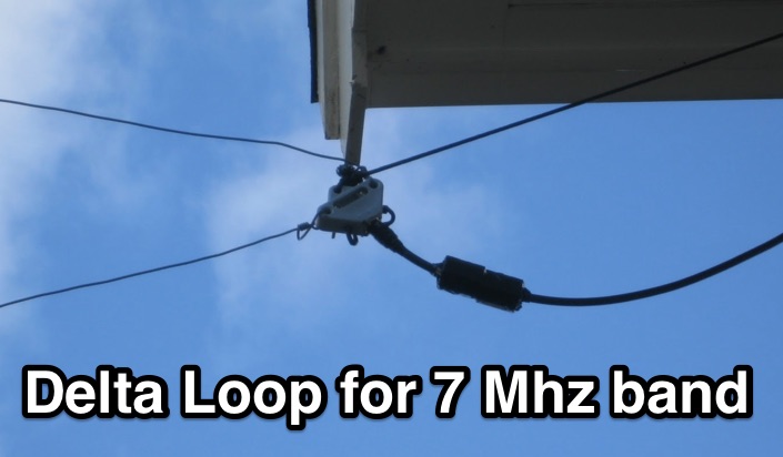 Antenna experiment a Delta loop antenna for 7 Mhz band
 -
 Extension to an existing fan dipole originally modeled for 40 20 and 6 meters. This modification will add 80 15 and 10 meter bands.
 -
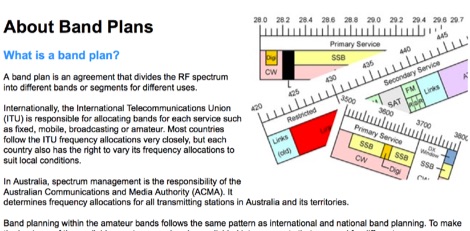 Australian amateur radio band plans in pdf format
 -
 An excellent introduction to ham radio bands, which bands to use and when.
 -
 Interesting article on multiband fan dipoles. This article give an overview on designing this wire antenna, and planning a robust installation and proper feed line. Includes notes on setting up a commercial fan dipole antenna and on how diy your own.
 -
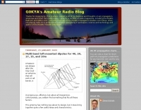 Multi-band loft-mounted dipoles for 40, 20, 17, 15, and 10m
 -
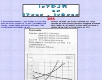 Demonstrates the construction of a _3MA triband mobile antenna_ designed by IZ7DJR, emphasizing a full-size quarter-wave whip for 10 meters. The design incorporates a rapid tilt-down mechanism to facilitate quick changes of loading coils for operation on 15 and 20 meters. This approach aims to minimize losses and enhance efficiency compared to conventional base-loaded mobile antennas. The resource provides specific coil winding data: 22 turns for 15 meters and **37 turns** for 20 meters, both using 1mm wire over an 80mm coil length. The 10-meter band operates without a loading coil, leveraging its full-size design. The author's design prioritizes ease of band switching and improved performance for mobile HF operations, offering a practical alternative to more lossy commercial options.
 -
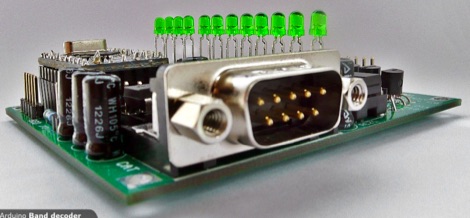 Arduino Band decoder project available in KIT
 -
 Part 2 You're now much closer to saying goodbye to your unwanted signal problems!
 -
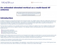 This article explores the performance of an unloaded elevated vertical, base matching and feed line as a multi-band HF antenna system.
 -
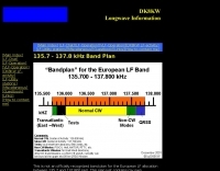 The 2.1 kHz wide European LF allocation between 135.7 and 137.8 kHz is detailed in this observed band plan, offering guidance for activity within this narrow segment. It specifically addresses the challenge of locating weak signals, such as those from Slow-CW stations, which can have bandwidths of only a few Hertz. The resource emphasizes the utility of precise frequency knowledge when operating with narrow DSP filters, like a 30 Hz filter for CW, to differentiate multiple stations within a very small band segment. The plan, though not officially recognized, provides practical orientation for operators, particularly those new to the _LF band_. It references a similar plan published by the _RSGB_ in the January 2000 issue of _RADCOM_, suggesting a community-driven approach to band organization. The content highlights the importance of spectral awareness, noting that multiple stations can occupy minimal bandwidth, a concept illustrated by spectrographic analysis.
 -
 A 5 band two element quad antenna working from 20 to 10 meters using hardware-store parts or modifying an existing commercial triband quad by KC6T
 -
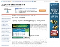 The basics of what is a discone antenna for wide band or bandwidth omnidirectional applications.
 -
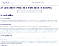 This article explores the performance of an unloaded vertical as a multi-band HF antenna.
 -
 Optimizing a G5RV or ZS6BKW multiband wire antenna for HF operation often involves addressing common SWR issues and understanding feedline characteristics. This resource chronicles the construction and performance evaluation of a G5RV, initially built for 80m, 40m, 15m, and 10m bands, by a newly licensed Foundation operator. The author details the selection of materials, including 3.5 mm stainless steel wire for the doublet arms and enameled copper wire for the open-wire feeder, and the initial decision to omit a balun based on common online information. The narrative highlights the initial disappointing performance, characterized by high receive noise and poor signal reports on 80 meters, despite the transceiver's internal ATU achieving a 1:1 match. This led to experimentation with a coax current balun and further research into G5RV myths, such as SWR claims and the necessity of a balun. The author then describes modifying the antenna to the ZS6BKW configuration, which involves specific changes to the doublet and feedline lengths, and integrating a 1:1 current balun wound on a ferrite toroid. The modifications resulted in improved reception and transmit performance across the bands.
 -
 A Loop Fed Array Yagi antenna for 50 MHz featuring 11 dBi gain and 23 f/b ratio. In this excellent page the author even includes a detailed drawing in DWG format, with element lenght and spacing measures, in a separa file a full list of material list needed to build this yagi antenna including source and price, the EZnec file for this antenna plan, and a lot of pictures of this LFA Yagi for 50 Mhz. A ten page PDF file containing all infos, is also available to download.
 -
 Single Coax Feed to Multi-Band Copper Cactus Antenna.
 -
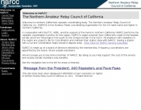 Details the Northern Amateur Relay Council of California (NARCC) as the regional coordinating body for amateur radio repeaters operating on the 10-meter band and above. It outlines NARCC's function in managing frequency allocations to minimize interference and ensure efficient spectrum use across Northern California. The resource specifies that NARCC operates in cooperation with the FCC and ARRL, indicating its recognized authority within the amateur radio community. The organization's role centers on repeater coordination, a critical aspect of VHF/UHF operations where multiple stations share limited frequency segments. It highlights the support received from local amateur radio operators, underscoring a community-driven approach to spectrum management. The site serves as a primary reference for hams seeking to establish or operate repeaters within the designated service area. NARCC's activities directly impact the operational landscape for _VHF_ and _UHF_ enthusiasts, providing essential guidelines and coordinated frequencies. This ensures orderly communication and prevents conflicts, particularly in densely populated areas of Northern California.
 -
 In this article, the author discusses the importance of good transformers for Beverages, especially for common-mode isolation. The author recommends #43 ferrite for the transformer, and provides the turns required for different core types. The author also recommends using lower permeability ferrites for better performance at lower frequencies.
 -
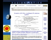 Unlocking the full multiband potential of the 225 Ohm elementary radiator in a folded monopole, dipole-like or turnstile layout, by Francesco Errante
 -
 Optimizing the ZS6BKW antenna for full HF band coverage often requires specific modifications beyond its standard configuration. This resource details several enhancements, beginning with a simple series capacitor to improve 80m SWR, a technique W5DXP found effective for permanent installation due to its minimal impact on higher bands. Further improvements include a 10-inch parallel open stub for 10m resonance, shifting the frequency to 28.4 MHz with an SWR of approximately 1.8:1, a practical solution for Technician class operators. The document then explores a switchable matching section, adding or subtracting one foot of ladder line at the 1:1 choke-balun, which significantly impacts higher frequency bands and eliminates the need for a tuner on 17m. W5DXP's _AIM-4170D_ antenna analyzer measurements confirm these effects. More advanced modifications involve a parallel capacitor for further 80m SWR reduction, requiring remote switching for multi-band operation, and relay-switched parallel capacitors at specific points on the 450-ohm matching section to achieve low SWR on 60m, 30m, and 15m. These detailed steps, including _Smith chart_ analyses for the challenging bands, aim to transform the ZS6BKW into a truly all-HF-band antenna, reflecting W5DXP's practical experience in antenna tuning.
 -
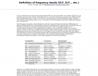 Definition of radio frequency bands, hf vhf uhf etc.
 -
 The resource presents a detailed schematic for constructing a dual-band vertical antenna, specifically designed for operation on the 2-meter and 70-centimeter amateur radio bands. It illustrates the physical layout, critical dimensions, and component placement necessary for successful replication. Key elements such as the radiating elements, phasing sections, and feed point are clearly depicted, providing a visual guide for radio amateurs undertaking a homebrew antenna project. The diagram specifies the lengths for the VHF and UHF sections, indicating how these elements are integrated to achieve dual-band functionality from a single coaxial feedline. It also implies the use of common materials readily available to most experimenters, focusing on simplicity and effectiveness in its design. The visual format of a GIF image ensures direct access to the construction details without requiring extensive textual interpretation. This schematic serves as a practical reference for hams interested in building a compact, efficient vertical antenna for local and regional FM communications, offering a proven design for immediate implementation.
 -
 Presents a QRP AM/CW transmitter project specifically designed for the 10-meter band, utilizing a crystal oscillator and a collector-modulated AM oscillator. The design employs a 2N2219(A) transistor in a Colpitts configuration, generating 100 to 350 mW of RF output power depending on the 9-18 Volt supply voltage and modulation depth. Frequency stability is maintained by a 28 MHz crystal, with fine-tuning possible via a Ct1 trimmer capacitor for approximately 1 kHz adjustment. The resource details the RF oscillator stage, implemented with a 2N2219 NPN transistor, emphasizing frequency stability and low power dissipation. It also covers the amplitude modulation stage, managed by a 2N2905 PNP transistor, which impresses audio information onto the carrier. Selective components (C3, C4, C7, C5) enhance voice frequencies within a +/- 5 kHz bandwidth, and modulation depth is controlled by R2 and R3. The project includes a 3-element L-type narrow bandpass filter (Ct3, L3, C10) to suppress harmonics and ensure a clean output signal. The project provides a complete schematic diagram, a comprehensive parts list including specific capacitor, resistor, and inductor values, and construction notes for the coils (L1, L2, L3). It also offers practical advice on enclosure requirements, suggesting an all-metal case or a PVC box with graphite paint for RF shielding. Operational parameters such as current draw (27mA@9V to 45mA@16V) and input impedance (50 Ohms) are specified, alongside guidance on antenna matching and the importance of a valid amateur radio license for 10-meter band operation.
 -
 The G7FEK Multi-Band Nested Marconi Antenna, a small, efficient all-band antenna.
 -
 The antenna is a VHF side is a 2m moxon, tuned on 145.825 MHz. The driven element of the moxon couples to a driven element for a 5 element 70cms Yagi, tuned on 436.5 MHz.
 -
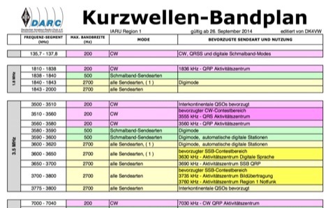 Kurzwellenbandplane der IARU Region 1 available in german and in english
 -
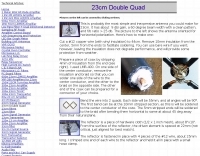 probably the most simple and inexpensive antenna you could make for 23cm.
 -
 The ZS6BKW multiband antenna, an optimized variant of the classic G5RV, features a 102-foot (31.1 m) horizontal span and a 39.1-foot ladder line matching section. This design, derived by G0GSF (formerly ZS6BKW) in the early 1980s using computer programs and _Smith charts_, aims for improved SWR across multiple HF bands compared to its predecessor. Construction details specify Wireman 554 ladder line and #14 AWG THHN copper wire for the radiators, with precise instructions for determining the velocity factor (VF) of the ladder line using an antenna analyzer or dip meter, ensuring accurate physical length for the matching section. The radiator length is electrically 1.35 wavelengths for the 20-meter band, requiring careful trimming during tuning. Field measurements with an _AIM-4170C_ analyzer by KI4PMI and NC4FB demonstrated good SWR curves and bandwidth on 6, 10, 12, 17, 20, and 40 meters. The antenna was deemed unusable on 15 and 30 meters due to very high SWR, but an LDG AT-100PRO autotuner successfully brought 6 and 80 meters into tune. Contacts were made on 80, 40, 20, and 17 meters, including a **17-meter** contact to Spain. EZNEC models for 80-6 meters are provided, along with an AutoEZ model by AC6LA, which predicted good SWR for 80-10 meters. W5DXP's modifications for an all-band HF ZS6BKW are also referenced.
 -
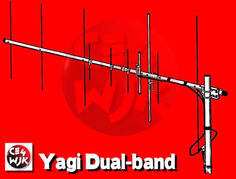
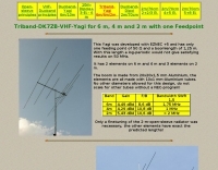 Triband DK7ZB VHF Yagi antenna for 6 m, 4 m and 2 m with a single feedpoint
 -
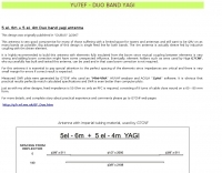 The original project of a dual band yagi antenna for 50 and 70 mhz, published on dubus 2/2007 by YU7EF
 -
 Band Plan for HF Bands by IARU Region 1, effective 2014.
 -
 Package contain 1x yaesu vx-8r 1x sma dual section antenna 1x hf antenna lithium ion battery pack fnb-101li 1x battery charger nc-86c 1x connector unit
 -
 Exagonal Beam antenna cover 20-17-15-10 meters By KE4NU
 -
 The SCOTIA Bandhopper, a multi-band mobile vertical antenna, offers a unique sliding coil design for rapid band changes across 10m to 80m. Drawing inspiration from the classic Webster _Bandspanner_, this design improves efficiency through near-center loading, theoretically achieving up to **2.25 times** greater radiation resistance than base-loaded counterparts. The antenna, extending to approximately 10 feet on 80m, utilizes a 5-foot fiberglass tube with an internal loading coil and a 57-inch tapered steel whip, allowing continuous tuning across bands without changing coils or whip sections. Field results from GM3VLB and the SCOTIA team, based on over 40 years of /M and /P operations, indicate the Bandhopper significantly outperforms shorter mobile whips. Its slim profile minimizes drag, making it suitable for sustained motorway speeds. The design incorporates a novel "fixed spring contact" arrangement for the variable inductance loading coil, with two sets of contacts for 10/12m and 15-80m. Construction details are provided, including materials like boundary marker poles and specific wire gauges, with an estimated build cost of **£20** or less, depending on junk box availability.
 -

-
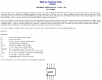
 Demonstrates how to construct an automatic band decoder, moving beyond manual selector switches for antenna and filter control. It addresses the challenge of varying band data outputs from different transceivers: Icom rigs provide voltage values, Yaesu rigs use Binary Coded Decimal (BCD), and Kenwood rigs lack direct band data output. The resource highlights a clever solution utilizing logging software like _CT (K1EA)_ and _DX4WIN_ to emulate Yaesu's BCD output via a PC's printer port, making the decoder compatible with any rig. The author details experiences building decoders based on designs by Bob _K6XX_ and Guy _ON4AOI_, noting K6XX's simple TTL chip design and ON4AOI's more comprehensive, opto-isolated unit capable of controlling ten outputs and bandpass filters like the _Dunestar_. It also references a _W9XT_ board design, which Steve Wilson, G3VMW, modified with BD140 transistors for source drivers, emphasizing safety. The author successfully cased an ON4AOI-based decoder in an old modem case, connecting it to an FT1000MP or a PC printer port to drive remote relays and a Dunestar Band Pass Filter.
 -
 To build a Band Decoder to drive our remote relays, we need to supply the band information from the rig to the decoder
 -
 An homemade fan dipole antenna for 20 30 40 meter bands, setup in a 15 meter wide garden. The longest leg for 40 meter is folded to fit in the 7.5 m
 -
 Lights on why 160 meters is so unpredictable and what is being done to reveal its secrets
 -
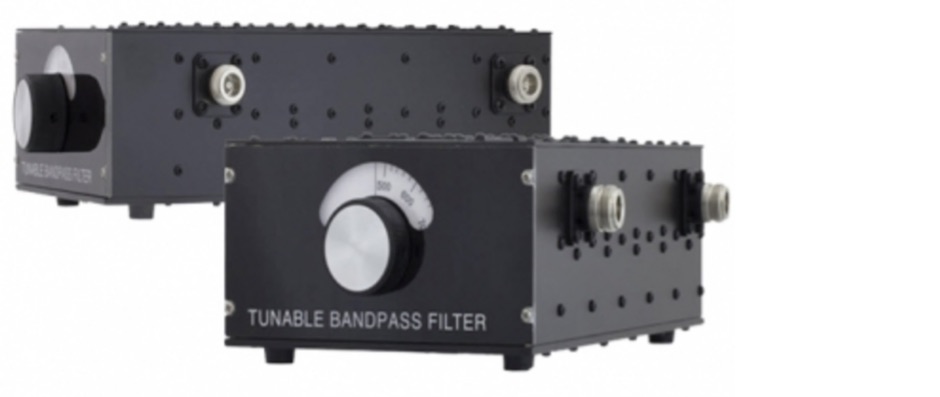 A homemade tunable bandpass filter for all HF bands from 160m to 10m
 -
 As the sunspots return and DX propagation conditions to improve, the age old problem with QRM begins to show up on the amateur bands. Thif filter help you on improving reception
 -
 Operating on the 11-meter band, the Alfa Tango Argentina website serves as a digital hub for CB radio DX enthusiasts, particularly those affiliated with the _Alfa Tango_ international group. The resource primarily functions as a community portal, facilitating connections among members and promoting activities related to long-distance CB communications. It presents basic information about the group's presence in Argentina and emphasizes the social aspect of radio communication, framing participants as "friends who have never met." The site's content reflects the operational focus on **DXing** within the CB radio sphere, a practice that mirrors amateur radio's pursuit of distant contacts. While specific operational data or technical guides are not detailed, the site's existence supports the organizational structure of the Alfa Tango group, which coordinates activities across various countries.