Search results
Query: antenna cal.
Links: 1264 | Categories: 63
Categories
- Antennas > 20M > 20 meter Vertical Antennas
- Antennas > 40M > 40 meter Vertical Antennas
- Antennas > Antenna Calculators
- Radio Equipment > HF Vertical Antenna
- Manufacturers > Antennas > VHF UHF Microwave > Vertical Antennas
- Manufacturers > Antennas > HF > Vertical Antennas
- Antennas > 6M > 6 meter J-Pole Antenna
- Antennas > 6M > 6 meter Yagi Antennas
- Software > Antenna analysis
- Antennas > Theory > Antenna Gain
- Shopping and Services > Antennas
- Antennas > Vertical
- Technical Reference
- Antennas > 160M
- Antennas > 17M
- Antennas > 20M
- Antennas > 30M
- Antennas > 40M
- Antennas > 70cm
- Operating Modes > Satellites > AO-51
- Technical Reference > Arduino
- Radio Equipment > Antenna Analyzers > Array Solutions AIM 4170D
- Antennas > Bazooka
- Operating Aids > Beginner's Guides
- Shortwave Radio > Beginner's guides
- Ham Radio > Regional > Brazil
- Radio Equipment > HF Vertical Antenna > Butternut HF2V
- Antennas > C-Pole
- Shopping and Services > CB Radio Stores
- Radio Equipment > HF Vertical Antenna > Cushcraft R5
-
 W1JR-style common mode chokes are versatile tools for antenna experimentation. Three variants were constructed using RK4 ferrite cores and RG303 Teflon coax, differing only in output terminals: banana connectors for dipoles, N-connectors for antennas with existing terminals, and bolts with washers for vertical antennas. Materials included junction boxes, terminals, and small hardware. Assembly involves maximizing windings on the core, securing with ties, and gluing components. Improvements included switching to multi-stranded wire for durability. These chokes provide efficient, customizable solutions for various antenna setups.
 -
 The tri-band trapped delta loop antenna design operates on 80 meters (3.5–4 MHz), 40 meters (7–7.3 MHz), and 30 meters (10.1–10.15 MHz) using a single triangular wire loop. This configuration eliminates the need for an external antenna tuner or band-switching relays. The antenna's physical perimeter, approximately 270 feet, establishes 80M as the fundamental band, with specific trap placements enabling resonance on 40M and 30M. Trap design and placement are critical, with 30M traps positioned inboard of 40M traps within the horizontal element. Each slant leg measures approximately 80 feet. The resource references foundational information from the _ARRL Antenna Handbook_ and _ON4UN’s Low Band DXing_ regarding full-wave loop behavior and feedpoint impedances. The project aims to provide multi-band HF operation from a single, fixed antenna structure.
 -
 Online antenna calculator for J-Pole models.
 -
 The Aziloop DF-72 antenna system provides 72 K9AY headings and 36 loop axes, allowing for rapid switching in 60 ms. It integrates a switchable 18 dB preamp, a 4-step attenuator (0-18 dB), and four 7-pole preselection filters to optimize receiver performance. The K9AY load is adjustable from 250 Ohm to 950 Ohm in 50 Ohm increments, offering flexibility for various receiving conditions. Control is managed via an intuitive Windows UI, supporting Local, Client, or Server modes, with headless remote operation possible through the built-in Ethernet Server. _Omni-Rig_ support facilitates auto-filter selection, PTT muting, and Rig-Sync functionality, enhancing integration with existing station setups. Designed by _GW4GTE_, the system utilizes a low visual impact, small-footprint antenna with orthogonal loops and an earth connection. It is suitable for general monitoring, co-channel station resolution, basic direction finding, and interference reduction across the VLF to HF spectrum.
 -
 Delta loop antennas, particularly the 30 meter variant, offer unique advantages in terms of vertical polarization and omni-directional coverage. The construction process detailed by VE3VN highlights common mechanical and electrical challenges faced by amateur radio operators. Key design considerations include minimizing interaction with existing contest band antennas, achieving low elevation angles for DX chasing, and ensuring the antenna remains off the ground for agricultural clearance. The article provides specific measurements, such as the loop's height and feed point impedance, which are critical for optimizing performance. The use of NEC modeling software illustrates the importance of accurate resonance calculations, revealing how proximity to the tower affects both pattern and impedance. This practical account serves as a resource for hams looking to build effective antennas while navigating typical construction hurdles.
 -
 The K5USS 6 Meter Hentenna Project page on Hamuniverse provides detailed instructions on how to build a 6 meter directional antenna with 3.5 dBd gain. The project is presented with permission from K5USS, Charlie of Richardson, Texas. This directional antenna is a full wave loop on 6 meters, horizontally polarized but mounted vertically, with a 50 ohm impedance, ideal for 6 meter SSB operations. The page is useful for hams looking to construct their own directional antenna for improved performance on the 6 meter band.
 -
 The article discusses the evolution of antenna designs, specifically focusing on the upgrade from the W7IUV rotatable Flag to the Waller Flag. Author Pierluigi Mansutti IV3PRK shares insights on modeling these antennas using EZNEC software, detailing their performance in noisy environments. The W7IUV Flag proved effective for receiving signals, while the Waller Flag, developed by NX4D and N4IS, offers improved front-to-back ratios but requires careful consideration of signal levels and noise management. The article emphasizes practical modeling results and interactions between different antenna setups.
 -
 Presents DJ5IL's personal amateur radio station, detailing his journey as a licensed operator since 1973. The resource covers his **shack setup**, including an Elecraft K4D, Icom IC-7610, and various vintage transceivers like the Drake 2-B, along with a SPE Expert 1K-FA amplifier. Antenna systems include a PRO.SIS.TEL RD1524T rotary dipole for 40/20/15/10m at 15m height, an 18m vertical dipole with an SGC SG-230 tuner for 3.5-30 MHz, and an inverted-V dipole for 80m. The site features a **QSL gallery** showcasing his custom card designs and outlines his QSL policy, emphasizing the exchange of unique, personalized cards over generic confirmations. It also includes a detailed operator's biography, tracing his early fascination with radio, obtaining his license at 16, and memorable QSOs, such as a contact with his blood-relative W3NZ. The resource also delves into the historical significance of amateur radio's role in pioneering shortwave communication following the 1912 International Radiotelegraph Convention, which initially relegated amateurs to wavelengths of 200 meters and shorter. DJ5IL's philosophy on "ham spirit" is discussed, stressing the unpolitical nature of amateur radio as a global fraternity.
 -
 The ICOM IC-705, a popular QRP transceiver for portable operations, often presents unique challenges for field deployment. This resource details practical solutions for common portable setup issues, particularly for _Parks on the Air_ (POTA) activations. It describes a custom bracket for connecting antennas to the IC-705 through a backpack's antenna flap, utilizing a BNC female-to-female chassis mount connector to mitigate cable tangles. The author shares experiences with a DIY magnetic loop antenna, noting its ease of tuning with the IC-705 and successful CW contacts on 40 and 20 meters over distances exceeding **1000 miles**. Another modification presented is a strain relief solution for the microphone cord, replacing the standard spring clip with an easier-to-attach method. The page also mentions using a _Wolf River Parks antenna_ for POTA activations and references the QRPGuys DS-1 antenna as another portable option. Firmware updates and integration with an LDG Z11-Pro II auto-tuner are also discussed.
 -
 This article from the July 1976 issue of Radio REF discusses the trend of large antennas for ham radio operators on the low bands. It specifically focuses on a Yagi 2 element antenna for the 80m band, detailing its construction and functionality. The author explains how the antenna can be switched between directing signals towards the West or East using a switch at the station. The article also provides technical details on the lengths of the director and reflector elements, and how they impact the antenna's performance. A useful resource for hams looking to build or understand Yagi antennas for the 80m band.
 -
 This page discusses the potential risks and safety concerns related to antenna installations for ham radio operators. It emphasizes the importance of following electrical codes and regulations to prevent property damage, injuries, or even loss of life. The author shares personal experiences and advises against using trees for antenna support near power lines. The content serves as a cautionary resource for hams planning antenna setups to ensure safety and compliance with regulations.
 -
 This article explores the powerful features of AutoEZ as an Excel application working with EZNEC antenna modeling software. The article demonstrates how variables, equations, and formulas enable versatile antenna design and automatic optimization. Through practical examples including dipoles, inverted vees, delta loops, and monopoles, the author shows techniques for achieving resonance, implementing transmission line resonators for broadbanding, and optimizing antennas across frequency ranges. The step-by-step demonstrations cover unit conversion, coordinate calculations, segmentation considerations, and SWR optimization. This practical guide illustrates how AutoEZ extends EZNEC's capabilities, making complex antenna modeling more efficient and accessible.
 -
 This page discusses the construction and design of a shortened 2-element Yagi antenna for the 40-meter band, focusing on the driven element. The author shares insights on adding hats to the coil to reduce losses and improve performance. The article also mentions the use of EZNEC modeling software and an AIM4170 analyzer for tuning. Amateur radio operators interested in such antenna design and optimization for the 40-meter band can find useful information and practical tips on this page.
 -
 This article details an Inverted-L antenna design optimized for 160-meter band operation, consisting of a 10m vertical section and a 28m horizontal section supported by Spiderpoles. Despite its relatively low height compared to the wavelength, the antenna has demonstrated impressive DX capabilities, achieving contacts up to 3,453 miles into Asiatic Russia. The system incorporates a Pi-Network ATU at the base for tuning flexibility. While modeling shows a radiation pattern favoring the South, practical operation indicates effective all-round coverage on Top Band.
 -
 This article demonstrates how to convert an existing tower into a dual-band vertical antenna for 80- and 160-meter DX operation. Using EZNEC modeling and practical design principles, the authors achieved a low-profile, efficient setup with a single coax feed line, no moving parts, and optimal radiation patterns. The system integrates an 80-meter vertical wire and a 160-meter shunt-fed gamma match for simultaneous operation. Detailed construction insights, including feed system and capacitor configurations, offer a reliable, full-legal-power solution.
 -
 The 2m 7 element Yagi antenna is a perfect beam antenna with 11dB gain and a front-to-back ratio of 20-25 dB. It has seven elements and requires a matching network built of 3/8" aluminum tubing and RG-8 cable. The gamma tube is adjusted to provide the best fit, and the gamma-driven element feeding clamp is tightened. If the beam is vertical, a non-conducting mast is utilized to prevent detuning and skewing of the radiation pattern. For optimal VHF operating, the antenna is installed at a height of 30 feet or higher.
 -
 DK4MJ's blog details numerous POTA activations and outdoor amateur radio operations, predominantly from Germany. The content focuses on practical experiences in the field, often involving portable setups and antenna deployments for various bands. Articles frequently describe specific station configurations, power sources, and operational challenges encountered during activations. Many entries include photographs of the operating environment and equipment, such as _portable antennas_ and transceivers, providing visual context to the operational narratives. The blog serves as a personal log of amateur radio adventures, sharing insights into effective portable operating techniques and station optimization for remote locations. Regular updates cover recent activations and related amateur radio topics.
 -
 The Beam project offers various features for controlling antenna rotators, including support for 2 or 4 line LCD displays, software or hardware clocks, open collector drives for azimuth and elevation control, and internal calculations for tracking the sun and moon. It can also track satellites and supports "Flip Mode" for inverted antennas. The 4-line version provides detailed readouts while the 2-line version offers a more compact display. New versions now support PWM and I2C H-bridge modes for adjustable speed control at the end of a move.
 -
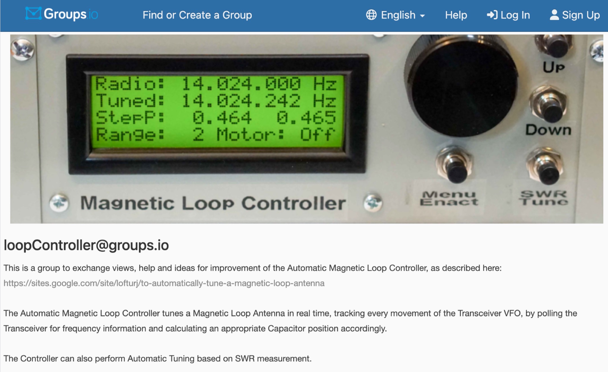 This is a group to exchange views, help and ideas for improvement of the Automatic Magnetic Loop Controller, as described at VE2AO web site. The Automatic Magnetic Loop Controller tunes a Magnetic Loop Antenna in real time, tracking every movement of the Transceiver VFO, by polling the Transceiver for frequency information and calculating an appropriate Capacitor position accordingly. The Controller can also perform Automatic Tuning based on SWR measurement.
 -
 This is a theoretical look at propagation on 630-Meters and 2200-Meters using ray tracing software. It expands on the brief discussion in the ARRL Handbooks. The Earth's magnetic field affects 630-Meter and 2200-Meter band propagation. Lower ionization reduces absorption, aiding low-frequency propagation. Differences exist between bands, limited daytime sky-wave propagation. Sunrise/sunset show promise, yet mechanisms are unclear. Ducting possible at night in specific conditions. Negative ions enhance propagation. Inefficient antennas and high man-made noise are anticipated. Groundwave propagation is significant on 2200-Meters.
 -
 Operating on the 60m band requires specialized antennas, and the 2 Element HB9CV, also known as the _ZL special_, excels in this domain. With a gain of **7.3 dBi** when phased at a 162-degree shift, it rivals traditional 3-element Yagi antennas, making it a solid option for enhancing 60m operations. The construction process is thoroughly detailed, providing insights into its performance and practical applications. Real-world comparisons demonstrate that the HB9CV antenna outperforms long Beverage antennas by an average of **5.5 dB** in reception, showcasing its effectiveness in various conditions. Insights from Mr. Cebik's analysis further validate its design, confirming its capability to maximize communication on the 60m band.
 -
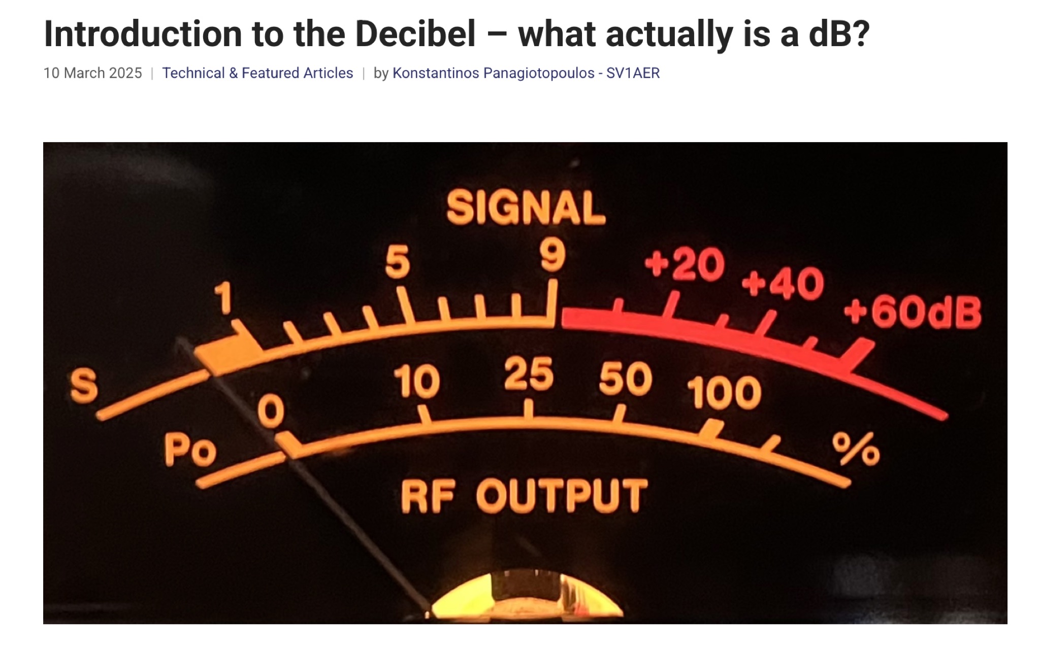 This article provides a comprehensive introduction to the decibel (dB), its logarithmic nature, and its applications in power, voltage, and antenna gain calculations. It explains how dB simplifies comparisons in electronics, telecommunications, and audio perception. The author clarifies key mathematical concepts, including power ratios, voltage doubling, and absolute levels like dBm and dBV. The discussion on S-units and antenna system gain is particularly relevant for radio amateurs. Overall, this is an informative and well-structured guide to understanding and applying decibels in technical fields.
 -
 A full-wave delta loop antenna, approximately 141 feet in total wire length for the 40-meter band, offers a low angle of radiation, which is highly advantageous for DX operations. This design, optimized for both 30m and 40m, leverages a specific circumference calculation of 1005/F, ensuring resonance on both bands through a simple switching mechanism. The antenna's configuration enhances long-distance communication, making it a practical choice for hams with limited space. The resource details the construction process, including the use of a _Ceramic Knife Switch_ for band selection and an _RG-11_ matching section to achieve optimal impedance. It outlines the precise loop lengths required for each band, along with tuning secrets to ensure efficient operation. Requiring a minimum height of 12 feet, this antenna can be supported by a single mast or tree limb, making it suitable for suburban installations where stealth or space constraints are a factor.
 -
 "The QRP Adventures of VE3FI" is a captivating blog that chronicles the amateur radio experiences of Bill, VE3FI, over two decades. Holding Canadian Basic, 5-word CW, and Advanced licenses, Bill's main interests include DXing and QRP operations. The blog offers detailed accounts of his portable activations, such as a recent outing in March 2025, where he achieved impressive DX contacts on the 10-meter band using just 8 watts and a Hamstick antenna. Bill's engaging storytelling and practical insights make this blog a valuable resource for both seasoned and aspiring amateur radio enthusiasts.
 -
 This resource details the construction and performance of a compact broadband magnetic loop antenna designed for portable receiving applications with devices like the _ATS MiniRadio_. The antenna utilizes approximately 3 meters of 0.5–1 mm copper wire wound in two turns on a rhomboidal wooden frame, measuring 50 cm by 70 cm. It connects via a modified 9:1 unun, where the primary center tap is isolated from ground to improve common-mode noise rejection. The design provides untuned operation across a frequency range from the longwave band up to approximately 25 MHz. Performance characteristics include observable directivity for noise suppression and the ability to connect directly to a radio or via a 50 coaxial cable for remote operation. The article specifies the unun's 3:1 turns ratio and its SMA output for connectivity. The methodology focuses on practical construction and observed reception quality.
 -
 This paper by Leif Asbrink (SM 5 BSZ) presents a practical approach to designing very high gain Yagi antennas, focusing on the "brute force" optimization method. The method, described in a previous article, ensures convergence independent of initial guesses. The paper provides detailed tables of element lengths and positions for Yagi antennas optimized for 144.1 MHz with a 50-ohm feed point impedance, aiming for minimal losses and high accuracy in comparisons.
 -
 This article describes the design and construction of a 4-meter band vertical sleeved dipole antenna, built to complement a newly acquired Yaesu FTDX10 transceiver. The simple yet effective antenna consists of modified coaxial cable housed in weather-resistant plastic conduit, featuring an integrated 8-turn choke coil. Despite common misidentification as an EFHW antenna, this design is actually a sleeved dipole that provides an excellent 50-ohm match across the band, achieving SWR values between 1:1 and 1.1:1. The project demonstrates an economical approach to entering the relatively quiet 4-meter band.
 -
 This project outlines a simple, cost-effective 40m band HF dipole antenna design, ideal for beginners. Constructed with insulated copper wire and a 1:1 balun, it offers a 50-ohm impedance, suitable for both 40m and 15m bands due to the harmonic relationship. Calculations account for a K factor, ensuring optimal length and performance. Antenna modeling with 4NEC2 confirms practical access to both bands, though real-world results may vary. Lightweight materials and straightforward assembly make it an accessible and versatile amateur radio solution.
 -
 This comprehensive article dispels common misconceptions about Standing Wave Ratio (SWR) in amateur radio. The author explains that SWR is not an antenna property but a measure of the entire antenna system, representing the mismatch between transmission line and load impedance. Contrary to popular belief, modest SWR values (under 3:1) typically cause minimal power loss in HF applications. The article demonstrates mathematically why obsession with achieving 1:1 SWR is often unnecessary, explains when SWR matters more (QRO, QRP, VHF/UHF), and explores effective matching techniques including proper ATU placement and quarter-wavelength transformers.
 -
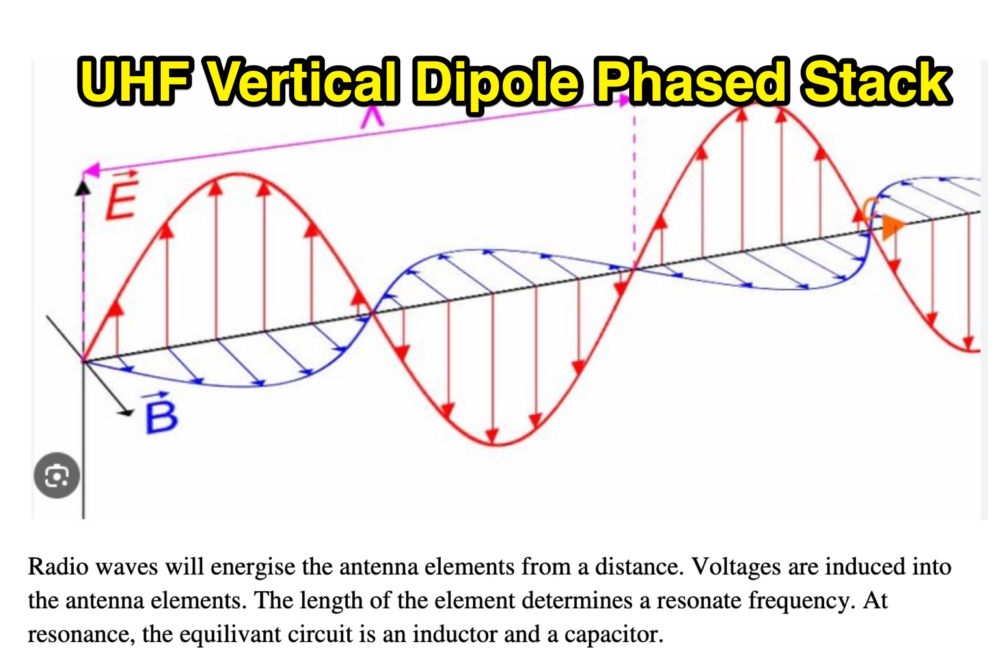 This PDF document discusses the setup and operation of UHF vertical dipole phased stack antennas for hams. It covers the advantages, principles, and practical aspects of using this type of antenna configuration. The document is a useful resource for amateur radio operators looking to improve their UHF station setup with phased array antennas.
 -
 VE1ZAC's analysis details the performance of **MFJ927** and **SGC239** autotuners with portable HF vertical antennas, specifically comparing 31 ft and 43 ft configurations. The resource originated from challenges encountered during a Maritime QSO Party roving operation, necessitating a lightweight and easily deployable antenna system. Target bands for the contest included 80, 40, 20, 15, and 10 meters, with a maximum power handling of 100 W CW. The author utilized a 30-foot carbon fiber push-up pole to support a vertical wire element, noting its 2 lb weight and reliability. EZNEC modeling was employed to predict performance, showing favorable results for a 30-foot vertical with elevated radials, particularly on 40 and 20 meters. Feedpoint impedance measurements, taken with an AIM4170C, are presented for various HF bands, both with and without a 41-foot RG6 stub designed to reduce reactance on 80 and 20 meters. The stub significantly improved matching on these bands, easing the tuner's workload. Operational tests revealed issues with the MFJ927's reliability during contest setup, leading to reliance on the K3's internal tuner. The SGC239, tested post-contest, performed flawlessly. A detailed side-by-side comparison covers mechanical aspects, connection options, power bias, impedance range, board quality, and documentation. Modifications to the MFJ927, including a new aluminum case, white paint for heat reduction, and upgraded impedance-measuring resistors, are also described.
 -
 The TY0RU DXpedition to Benin in 2022 achieved over **100,000 QSOs** from Cotonou, IOTA AF-051, operating across 160m through 6m bands using CW, SSB, and FT8 modes. The operation involved a team of 12 operators, including _F5RAV_, _F4WBN_, and _F1TCV_, utilizing multiple stations with transceivers like the Icom IC-7300 and IC-7610, paired with amplifiers and various antennas such as verticals, dipoles, and a 4-square array for 40m. The expedition's log is available on Club Log, supporting OQRS for both direct and bureau QSLs, with F5RAV serving as the QSL manager. The site details the team's travel, setup, and operational challenges, including local conditions and equipment deployment, offering insights into the logistical complexities of activating a rare DXCC entity. Donors are acknowledged, and a photo gallery documents the activity.
 -
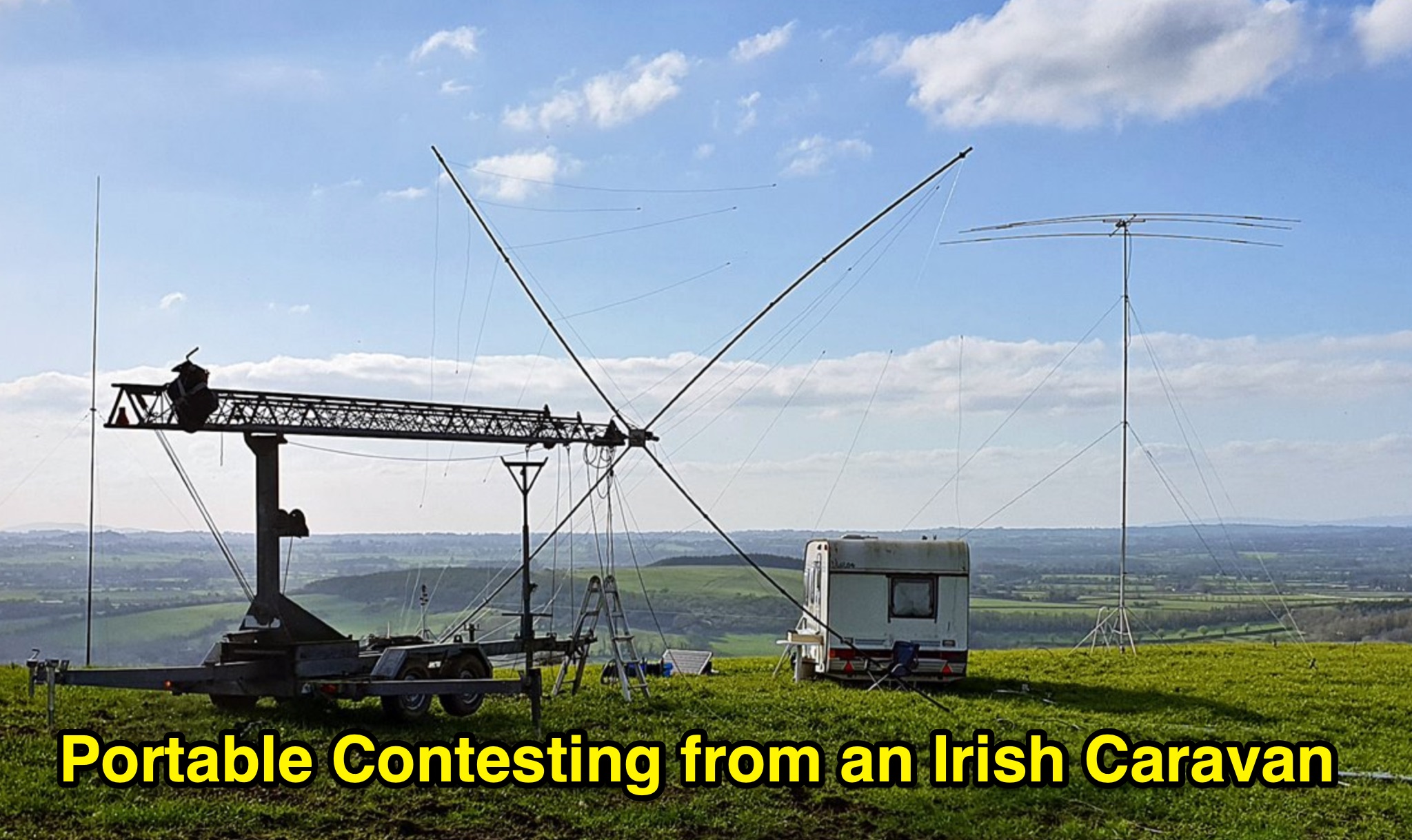 This blog chronicles over a decade of portable HF contesting from rural Ireland (2008–2019) by Olivier, operating under callsigns EI/ON4EI, EI8GQB, EI1A, and EI7T. Using only green energy from a caravan, he achieved top-tier results in major international contests—including 1st World in the 2018 IARU HF Championship (SSB LP) and multiple 1st-place finishes in CQ WW and CQ WPX SSB Europe. Operating in the demanding Single Operator All Band Low Power and SO2R categories, he deployed up to five antennas across five bands, often in remote or emergency-style conditions. The narrative blends technical detail, fieldcraft, and personal reflection, documenting triumphs, setbacks (including carbon monoxide poisoning), and the logistical challenges of sustainable portable operation—culminating in his decision to transition to team-based contesting and future DXpeditions.
 -
 This article explores the role of velocity factor (VF) in calculating stub lengths for VHF/UHF Baluns. It clarifies misconceptions about VF's relevance, distinguishing between coaxial cable interior fields and external stub fields. Practical examples, such as the Pawsey Stub and Coaxial Cable Balun, are analyzed alongside experimental findings. The results reveal that traditional VF adjustments are unnecessary for stubs with external fields but critical for internal coaxial applications. Historical and theoretical insights provide a comprehensive perspective for antenna enthusiasts and designers.
 -
 This project describes a high-performance EME antenna array consisting of two home-designed 9-element Yagis, each about 2.5 wavelengths long, combined into a 25-ohm system and matched to 100 ohms using 9/4λ sections of 50-ohm coax. The array supports rotatable polarity from 0° to 180°, allowing both horizontal and vertical polarization to optimize moonbounce performance under varying conditions. Despite operating for years without a balun—something another designer called “disastrousâ€â€”the system has delivered strong results, including copying very weak DX such as VK3KH at about -25 dB with only 120 W (around 2 kW ERP). The builder continues to refine the mechanics, having installed new gear motors and an upgraded follow-up control system in 2011.
 -
 Andrew Roos (ZS6AA) details his practical approach to building a Single Operator Two Radio contest station within suburban constraints. The article explains how he leveraged a Force-12 C-31XR triband beam's unique separate feed arrangement to operate on two bands simultaneously. Using band-pass filters and an antenna switch, he achieved sufficient isolation between bands without requiring multiple towers. The setup includes automatic band selection, audio switching, and computer control. Testing during the 2007 CQ WPX CW contest confirmed the system's effectiveness, demonstrating that competitive SO2R operation is achievable with limited space and budget.
 -
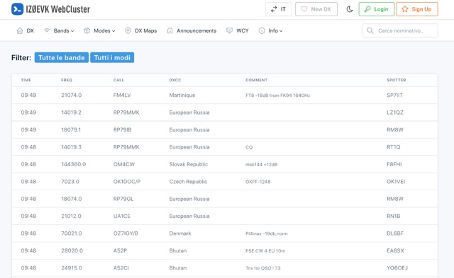 DX web cluster that offers features for both registered and unregistered users. Unregistered users can view spots, filter by band and mode, search for callsigns, while registered users get all that plus the ability to submit spots, upload logs, see DXCC country status, antenna pointing info, real-time maps of spots, email alerts for DXCC countries on-air, and more. Basically, register for free to get the full DX cluster experience.
 -
 Twenty 1-watt carbon film resistors are configured in parallel to construct a 50-ohm **dummy load** for amateur radio applications. The design incorporates a heatsink for thermal dissipation and an **SO-239 connector** for RF input, making it suitable for QRP operations. This budget-friendly project details component selection, soldering techniques, and mounting procedures, achieving a continuous power rating of 10 watts and intermittent handling of up to 100 watts across HF and VHF frequency ranges. The resource provides a step-by-step guide for assembly. This construction offers an economical solution for essential shack tasks such as antenna tuning, transmitter testing, and SWR meter calibration without radiating an RF signal. The utilization of readily available components significantly reduces the overall build cost compared to commercial alternatives, providing radio amateurs with a functional and reliable test accessory. While specific VSWR measurements are not provided, the design prioritizes practical utility for low-power transceiver diagnostics and general RF experimentation.
 -
 Operating amateur radio satellites presents unique challenges, particularly concerning antenna design and signal propagation. Juan Antonio Fernández Montaña, EA4CYQ, recounts his three-year journey into satellite communication, starting with initial guidance from EB4DKA. His early experiments involved a portable 1/4 wave VHF antenna with four 1/4 wave ground planes, designed for hand-held use to adjust polarity. This setup, paired with an FT-3000M transceiver, allowed full-duplex operation on **VHF** transmit and **UHF** receive, proving effective for early contacts on satellites like AO27, UO14, and SO35. EA4CYQ's experience highlights the critical role of coaxial cable loss and antenna polarization. After encountering significant signal degradation with longer RG213 runs, he experimented with a 1/2 inch commercial cable, noting improved reception but persistent fading due to varying satellite polarities. This led to the construction of an **Eggbeater II** antenna, an omnidirectional UHF design offering horizontal polarization at the horizon and circular right polarization at higher elevation angles. Subsequent modifications resulted in the directional **TPM2** antenna, which provided sufficient gain for LEO satellites with a wide 30-degree lobe, enabling consistent contacts from his home station. The article concludes with practical insights on the performance of the Eggbeater II for both UHF and VHF, and the TPM2 for UHF, emphasizing their utility for portable and fixed operations. EA4CYQ's journey underscores the iterative process of antenna development and the importance of adapting designs to overcome real-world propagation challenges in satellite communications.
 -
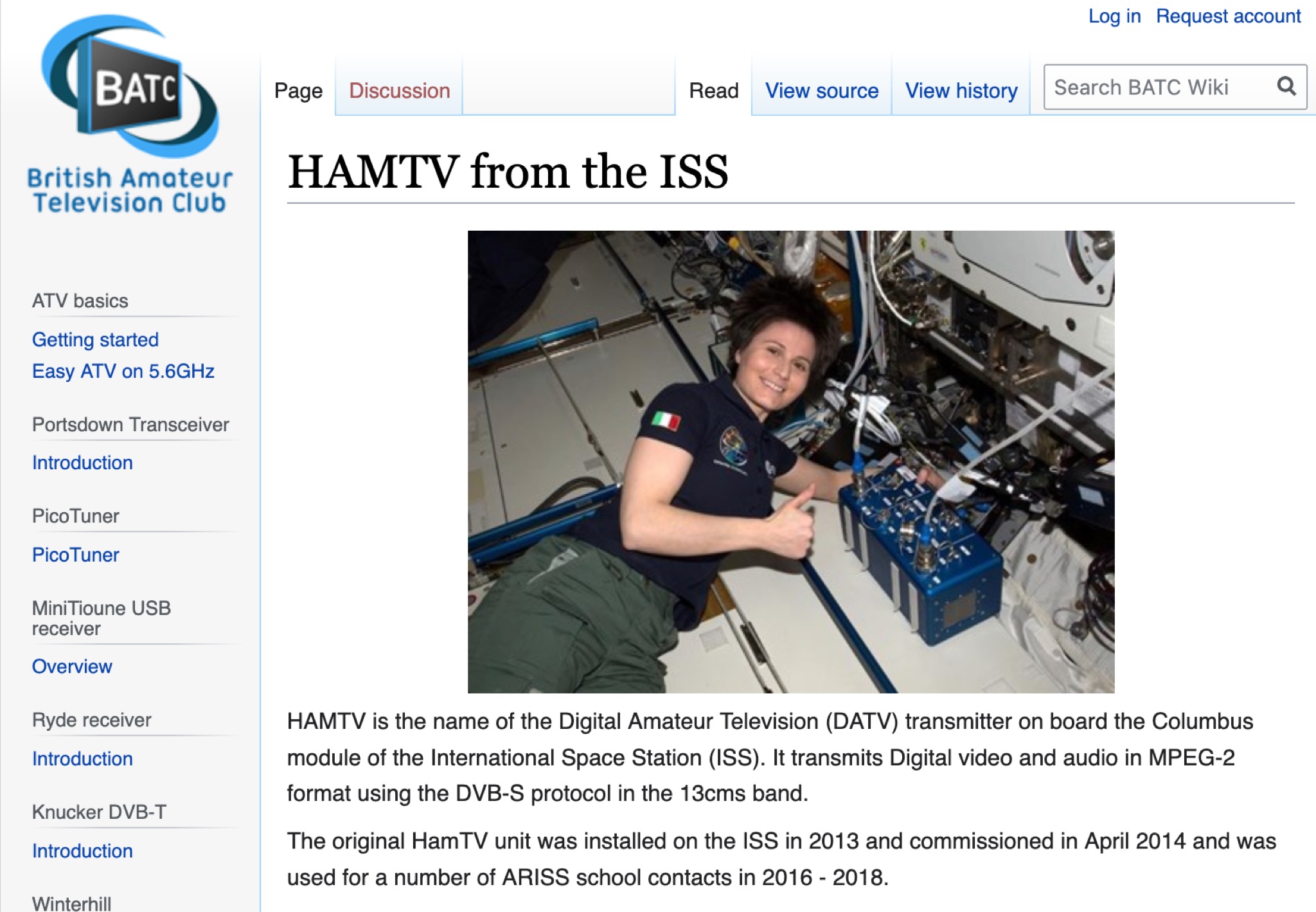 Learn about the HAMTV Digital Amateur Television (DATV) transmitter on the International Space Station (ISS), transmitting video and audio in MPEG-2 format using the DVB-S protocol. Discover its history, installations, failures, and repairs, as well as the current status and live video feed. Explore the technical details and challenges of the HAMTV transmitter, including power output, polarization, and antenna location. Find recordings of previous transmissions and understand the potential signal reflections caused by various ISS components. Stay updated on the latest developments and activities related to HAMTV from the ISS.
 -
 This resource presents a non-rigorous evaluation of the front-to-back (F/B) ratio of short Beverage antennas, specifically designed for low-band operation on frequencies such as 160, 80, 40, and 30 meters. The author, VE1ZAC, details the methodology used to measure the F/B ratio, which involves using a Millen Grid Dip Oscillator as a portable signal source. Measurements were taken by switching the antenna direction and recording S Meter and preamp readings to derive gain numbers. The document discusses the challenges faced in achieving accurate measurements and the assumptions made during the process, such as the calibration of S Meter units at 6 dB. This evaluation is particularly relevant for amateur radio operators interested in antenna performance on low bands.
 -
 This page by Arctic Peak provides a detailed explanation on how to use quarter-wave transmission lines as impedance transformers in ham radio antenna work. It explains how to match impedance values by connecting them with a λ/4 transmission line. The page also offers guidance on constructing your own transmission lines with specific impedance requirements, along with a calculator to determine the quarter wave length based on velocity factor and frequency. Useful for hams looking to optimize antenna performance and match transmission line impedance effectively.
 -
 This page provides a detailed guide on the J-pole antenna, an end-fed half-wave antenna matched to the feedline by a quarter-wave transmission line stub. It covers the characteristics, construction materials, feeding options, and mounting considerations for optimal performance. The information is useful for hams or amateur radio operators looking to build and set up a J-pole antenna for improved transmission and reception.
 -
 Details the construction and performance of a phase-controlled receiving array, specifically a **MicroSWA** variant, optimized for QRP low band fox hunting on 40M and 80M. The resource documents the author's iterative design process, addressing significant regional noise challenges encountered during 0100-0230 UTC fox hunt periods. Initial experiments involved a director wire on a 40M vertical, yielding limited improvement, prompting a shift towards advanced null-steering techniques. The project leverages concepts from Victor Misek’s "The Beverage Antenna Handbook" and Dallas Lankford’s extensive work on phased receiving antennas for urban lots. A key modification involved integrating a new passive phase control box and a push-pull **Norton common base preamp** using 2N5109 transistors, designed for high third-order intercept performance to maintain weak signal integrity amidst strong adjacent signals. The system incorporates Faraday-shielded transformers with RG174 primaries on -75 ferrite cores, housed in ABS plastic pipe. Performance tests confirmed the MicroSWA's ability to produce deep, steerable nulls, achieving approximately 30 dB noise reduction on 160M, 80M, and 40M. This enabled detection of QRP signals undetectable on conventional transmit antennas. The final unit includes front panel controls, a 10-11 dB preamp, and a robust power conditioner, demonstrating effective noise mitigation for challenging low band QRP operations.
 -
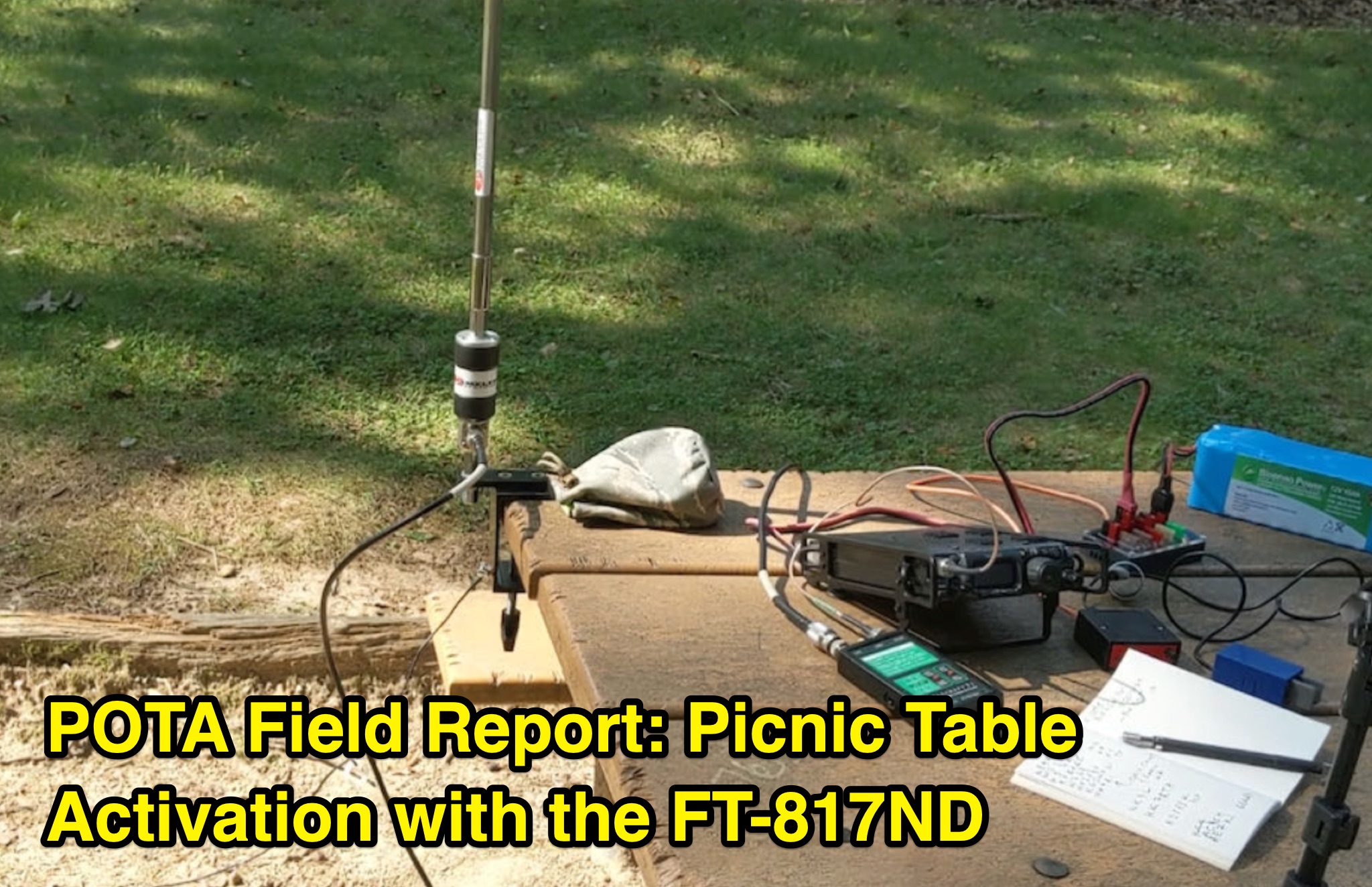 Read about a ham radio operator's experience activating a POTA site at the Folk Art Center using the Chameleon MPAS Lite vertical antenna and the Chameleon Universal Clamp Mount (CHA UCM). Discover how the author carefully deploys antennas to avoid interference with other park visitors and learn about the features of the CHA UCM, a simple antenna clamp mount. Follow along as the author shares their setup and operating spot choices to maximize their portable radio experience while enjoying the peaceful surroundings of the Blue Ridge Parkway.
 -
 Tracing the foundational work of Guglielmo Marconi, this article details his early laboratory experiments in 1895, where he successfully transmitted wireless signals over 1.5 miles. It highlights his 1896 patent for a wireless telegraphy system in England and subsequent demonstrations, including signal transmissions up to 6.4 km (4 miles) on Salisbury Plain and nearly 14.5 km (9 miles) across the Bristol Channel. Marconi's work built upon the mathematical theories of _James Clerk Maxwell_ and the experimental results of _Heinrich Hertz_, proving the practical feasibility of radio communication. The resource further chronicles the formation of The Wireless Telegraph & Signal Company Limited in 1897 and Marconi's relentless efforts to popularize radiotelegraphy. A significant milestone was the 1901 transatlantic reception of the Morse code letter "S" from Poldhu, Cornwall, at St. John's, Newfoundland, using a kite-supported wire antenna, defying contemporary mathematical predictions about Earth's curvature limiting range. This achievement underscored the global potential of radio. The article also touches upon Marconi's later discoveries, such as the "daytime effect" concerning atmospheric reflection of radio waves, and his 1902 patent for a magnetic detector, which became a standard wireless receiver. His contributions earned him a Nobel Prize in 1909.
 -
 Early 20th-century transatlantic wireless communication efforts involved distinct technical approaches by Reginald Fessenden and Guglielmo Marconi. Marconi's systems, operational until approximately 1912, primarily utilized _spark technology_ for wireless telegraphy, facilitating Morse code communication between ships and across oceans. His Poldhu station in December 1901 radiated signals in the MF band around 850 kHz, later evolving to 272 kHz in October 1902, and eventually 45 kHz by late 1907 with increasingly larger antenna structures like the pyramidal monopole and capacitive top-loaded arrays. Fessenden, conversely, focused on _continuous wave transmission_ for wireless telephony, recognizing its necessity for speech. His transatlantic experiments in 1906 employed synchronous rotary-spark-gap transmitters and 420-foot umbrella top-loaded antennas at Brant Rock, MA, and Machrihanish, Scotland, tuned to approximately 80 kHz. Fessenden later utilized the _Alexanderson HF alternator_ at 75 kHz by late 1906 for pure CW transmission, integrating a carbon microphone for amplitude modulation. Receiver technology also differed, with Marconi initially relying on untuned coherer-type detectors, later developing the magnetic detector in 1902, while Fessenden's CW approach necessitated more advanced detection methods.
 -
 This study analyzes the antenna pattern of the Utah Amateur Radio Club's 146.760 MHz repeater following antenna relocation in 1997. Noting degraded transmission toward the north, a customized signal mapping system using a Yaesu FT-817, GPS, and software was developed to log real-time signal data. Calibration techniques extended the radio's signal range, enabling precise field measurements. The method allowed continuous signal strength monitoring while driving, revealing anomalies in coverage likely due to tower modifications. Findings helped assess and visualize the antenna’s actual radiation pattern and highlighted environmental impact on signal distribution.
 -
 SAT filters ensure effective full-duplex satellite QSOs by mitigating interference between 145 MHz uplink and 435 MHz downlink signals. Custom coaxial and SMD-based filters address transmitter harmonic interference and improve receiver isolation, achieving over 70 dB suppression in the undesired band. Designed for simplicity, these filters maintain optimal VSWR and are housed in shielded brass enclosures. Practical implementations with Yagi antennas demonstrate compatibility with SDR systems, enabling seamless communication even in challenging satellite conditions, such as low-elevation passes and DX pile-ups.
 -
 Demonstrates the construction of an active loop converter specifically designed for the Low Frequency (LF) bands, addressing common localized noise interference in LF reception. The design integrates a sharply tuned circuit and a tuned loop antenna, utilizing the loop as the sole tuned inductive element. By applying positive feedback, the converter significantly increases the loop's effective Q, achieving factors between 1000 and 2000, which sharpens tuning and reduces noise. The circuit employs an _NE602_ mixer stage, feeding its output to an HF receiver, with a crystal-locked local oscillator at 4 MHz. A 20-turn, 0.8-meter square loop antenna with 500 uH inductance is detailed, connected via 2 meters of figure 8 flex cable. The converter offers three selectable frequency bands: 195-490 kHz, 150-220 kHz (including the New Zealand amateur band), and 128-160 kHz (covering the European amateur band). Performance measurements indicate an effective 3dB bandwidth of approximately 100 to 200 hertz at 200 kHz. The article provides insights into component selection, including an _LF353_ op-amp and a trifilar wound transformer on a ferrite core. Sensitivity figures are presented, showing 7.5 uV of converted output per 1 uV/meter signal strength into a 50-ohm load, or 37.5 uV into an _FRG7_ receiver, highlighting its capability to extract weak signals from noise.