Search results
Query: Construction
Links: 516 | Categories: 52
Categories
- Antennas > Baluns > 1 to 1 Balun
- Antennas > 15M
- Antennas > 17M
- Antennas > 20M > 20 meter Dipole Antennas
- Antennas > 20M > 20 meter Vertical Antennas
- Antennas > 20M
- Antennas > 23cm
- Antennas > 30M
- Antennas > Baluns > 4 to 1 balun
- Antennas > 40M > 40 meter Dipole Antennas
- Antennas > 40M > 40 meter Loop Antennas
- Antennas > 40M > 40 meter Magnetic Loop Antennas
- Antennas > 40M > 40 meter Vertical Antennas
- Antennas > 40M
- Antennas > 6M > 6 meter Moxon Antennas
- Antennas > 6M > 6 meter Yagi Antennas
- Antennas > 70cm
- Antennas > Antenna Books
- Technical Reference > Antenna Switch
- Technical Reference > Attenuators
- Technical Reference > ATV
- Technical Reference > Batteries > Battery Charger
- Antennas > C-Pole
- Antennas > Coils
- Antennas > Dipole
- Technical Reference > Duplexers
- Antennas > End-Fed > End Fed Half Wave Antenna
- Antennas > Receiving > EWE
- Operating Modes > GPS
- Antennas > Halo
-
 Four distinct amateur radio bands, specifically 40, 30, 20, and 15 meters, are addressed by a portable dipole antenna design. This antenna utilizes a manual switching mechanism, employing "fast-on" or flying connectors to change bands. The design is presented with an animated plan, illustrating how operators can adjust the operating frequency by opening and closing specific connections on the antenna elements. The resource describes a _4 savos dipol_ (4-band dipole) that can be shortened for specific band operation. It provides practical information for hams seeking to construct a versatile, multi-band wire antenna for portable operations or fixed station use. This design offers a straightforward approach to achieving multi-band HF capability without complex tuning units, making it suitable for field deployments like SOTA or POTA activations where rapid band changes are beneficial.
 -
 Newsletter article detailing the step-by-step construction of a 2m Hentenna using copper pipes, including user experiences and performance evaluations
 -
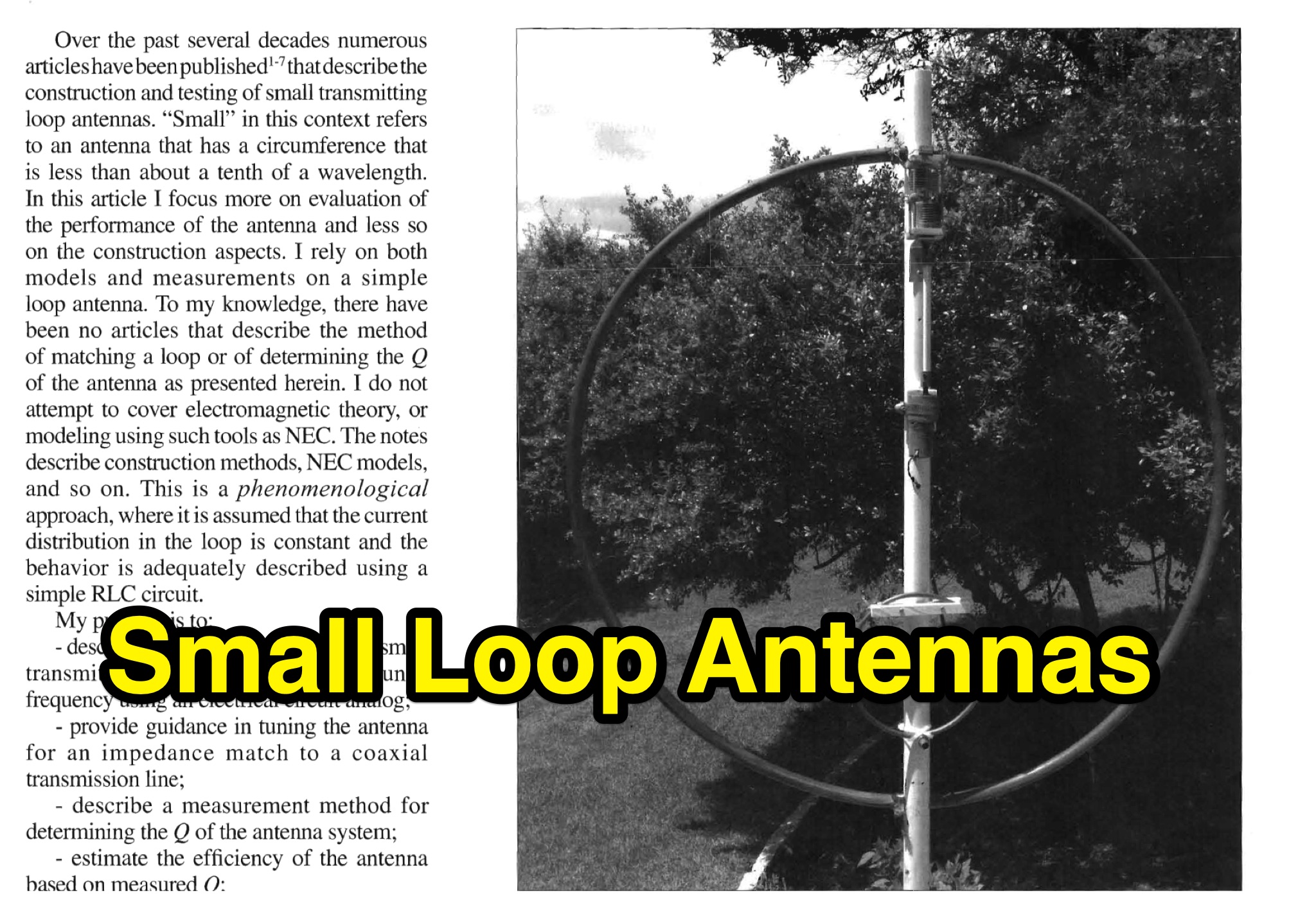 This PDF document provides detailed information on small loop antennas for hams. It covers the design, construction, and usage of small loop antennas for amateur radio operators. The guide includes practical tips and recommendations for optimizing the performance of small loop antennas in various operating conditions. Whether you are a beginner or an experienced ham radio operator looking to improve your antenna setup, this guide has valuable insights to offer.
 -
 This project explores the construction and performance of an Alford Loop antenna as an alternative to a round loop. The Alford Loop, symmetrically fed at opposite corners, behaves like a small loop despite its larger size. Built using PVC pipes and secured with tire wraps, the antenna integrates an LZ1AQ active amplifier for optimal performance. With deep nulls in its horizontal radiation pattern and improved resonance characteristics, this design has significantly outperformed previous active antennas in reception quality.
 -
 This project documents the construction and enhancement of a 30m Vertical Dipole Array (VDA) antenna inspired by Remco 7QNL article. Initial design utilized an 18m Spiderbeam pole and a 4m boom. Improvements included a lighter boom structure using fishing rods and a revised coaxial arrangement for enhanced mechanical stability.
 -
 The article describes the construction of a 1:49 impedance transformer designed to match the high impedance (around 2500Ω) of an end-fed half-wave (EFHW) dipole antenna to the 50Ω impedance of a typical transceiver. The EFHW is a popular portable antenna due to its simple construction, but feeding it can be challenging compared to a center-fed dipole. The transformer was built using an FT240-43 ferrite toroid core, with 2 primary and 14 secondary windings for a 1:49 impedance ratio. A capacitor was added in series with the primary winding to improve performance at higher frequencies. The author compared versions with one and two cores, and found that 100pF worked best for the single core design while 200pF was optimal for the dual core transformer.
 -
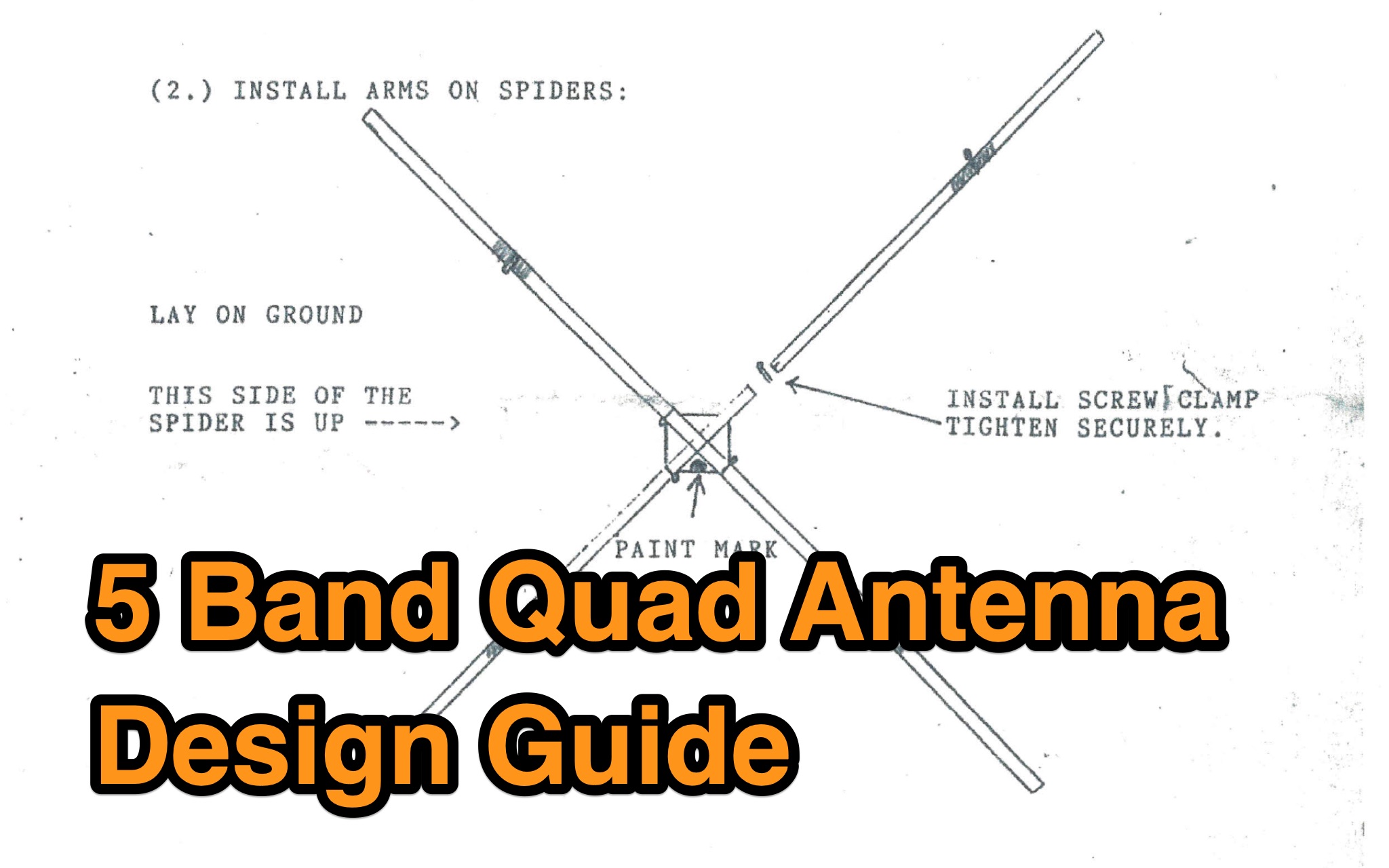 This guide provides detailed information on designing a 5 Band Quad Antenna for ham radio operators. It covers the necessary materials, dimensions, and construction steps required to build the antenna. The guide aims to help hams optimize their antenna setup for maximum performance on five different bands. Whether you are a beginner or an experienced operator, this resource can assist you in creating an effective antenna system for your station.
 -
 The 222 MHz Transverter project, based on Zack Lau's (W1VT) original July 1993 QEX magazine design, provides an IF of 28 MHz for both transmit and receive paths. Rick Bandla (VE3CVG) contributed supplemental notes and construction details, including modifications to achieve 10 mW output power from an initial 4 mW PEP. The design incorporates three distinct boards: a Local Oscillator (LO), a Transmitter (Tx), and a Receiver (Rx), with an estimated parts cost of just over $150 CDN, significantly less than commercial kits. Construction involves both through-hole and surface-mount components, with specific guidance on mounting MAV and MAR devices, grounding techniques, and component selection. The project details include parts lists, schematics for the LO, Tx, and Rx, and board layouts. Troubleshooting advice emphasizes sequential testing, starting with the LO, then Tx, and finally Rx, using a 194 MHz and 222.100 MHz capable FM handheld for signal tracing. Further enhancements are discussed, such as an optional Tx driver stage to boost output to 100 mW and the potential modification of a Motorola Maxor 80 PA for 222 MHz SSB/CW operation. The resource also covers practical aspects like power attenuation pads for IF radios (e.g., FT817) and considerations for enclosure design, including repurposing a Maxor 80 case. Performance reports indicate successful 70 km contacts with only 4 mW output.
 -
 The document details the construction and performance of a rotatable flag antenna designed for a small lot. The 7x14 feet flag, built with fiberglass poles and an aluminum hub, shows improved reception compared to the author's previous transmit antenna. Key components include a conventional transformer for impedance matching and a variable resistance termination system to optimize performance. Despite challenges like nearby objects affecting signal patterns, the antenna consistently provides better signal-to-noise ratios, making it a valuable addition for low-band listening in suburban areas.
 -
 This project details the construction of a compact, circularly polarized Quadrifilar Helix Antenna (QHA) designed for 146 MHz operation. The antenna features a 1/2λ1/2λ helical design with a 2.6:1 aspect ratio, providing 4.5 dB gain and a spheroid radiation pattern. It is ground plane independent and compatible with both vertical and horizontal polarizations, making it ideal for terrestrial and space communications. The design includes step-by-step instructions for building the antenna using readily available materials like aluminum rods, PVC pipes, and RG-58 coaxial cable. The antenna's performance has been validated through comparisons with commercial omnidirectional antennas, showing superior results.
 -
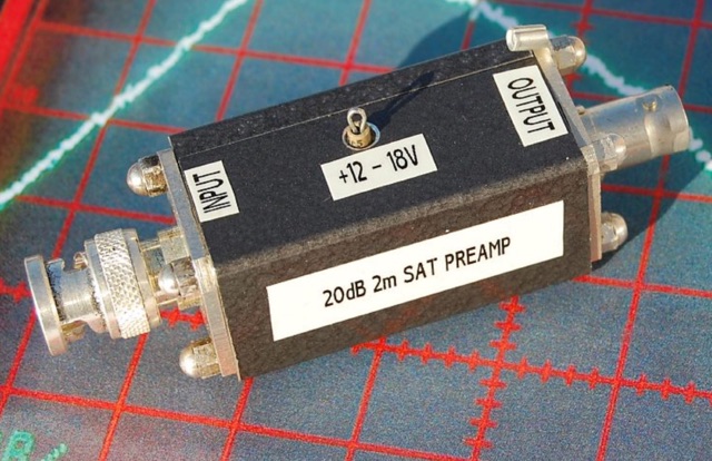 Here are some hints and tips for construction of a good preamp for satellite work.
 -
 The article describes the construction of a Lindenblad antenna, which is well-suited for receiving signals from low-orbiting weather satellites. The key points are: The Lindenblad antenna has an omnidirectional horizontal radiation pattern and is optimized for low to medium elevation angles, making it ideal for tracking passing satellites near the horizon. It is designed to receive circular polarization, which is common for weather satellite signals. The antenna is constructed using 4 folded dipole elements arranged on a cross-shaped frame. The necessary materials include a plastic junction box, PVC tubing, and aluminum rods to form the dipole elements. The article provides detailed instructions for preparing the components, assembling the dipoles, and connecting the feed lines to create the complete antenna. The completed antenna can be mounted on a vertical support, with the dipole elements angled at 30 degrees from horizontal, to optimize reception of the passing satellites. The author notes that the design was originally published in a now-defunct magazine, Meteo Satellite Inf", in 1993
 -
 Initially planned as an article on the R-407 station mast, this project evolved into creating a custom mast kit. Utilizing original materials, the design was modified for cost-effectiveness and practicality in home assembly. The new mast extends to 10 meters, featuring secure connections, a leather-lined base to prevent metal-on-metal friction, and sturdy military-grade anchors. Modifications include lengthened connecting tubes, improved anti-rotation features, and a convenient base design for solo assembly. Ideal for amateur radio operators, this mast provides stability, ease of construction, and versatility, proving more economical than professional products without compromising on performance or reliability. Article in Czeck.
 -
 The article details the C-Pole antenna project, emphasizing its portability and ease of setup for amateur radio operators. Key features include its compact design as a vertical half-wave dipole that requires no radials, making it functional at various locations. The antenna employs capacitive loading to reduce physical length while maintaining efficiency. It includes practical advice on resonance tuning, impedance matching, and construction materials, along with a calculator for determining dimensions based on desired frequencies. Overall, it presents a user-friendly solution for portable ham radio communication.
 -
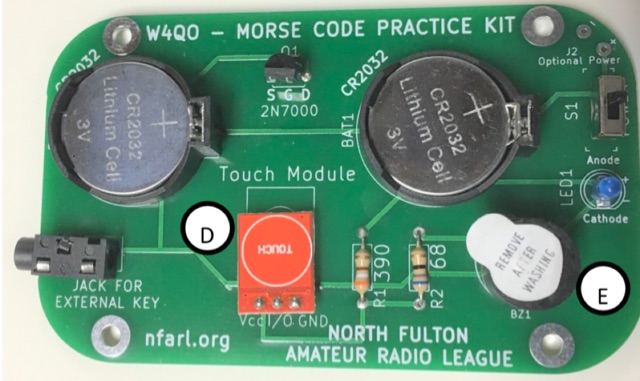 The Code Practice Oscillator kit, featured at TechFest 2020, provides a straightforward device for Morse Code skill development. It utilizes two 3V coin batteries for power and is designed for ease of construction, making it accessible for hams of various ages. The kit's primary technical substance revolves around generating an audible tone for practicing Morse Code timing and ear training, with a downloadable schematic detailing its electronic configuration. Construction of the oscillator involves soldering, with adult supervision recommended for younger builders. The kit's practical application lies in offering a hands-on method for beginners to learn Morse Code and for experienced operators to refine their sending abilities. Instructions for assembly are available as a downloadable PDF, complementing the schematic to guide users through the building process.
 -
 Constructing an effective antenna support system often involves safely elevating wire antennas into trees or over obstacles. This resource details the build process for the WT8WV "Colossus" air cannon antenna launcher, a pneumatic device designed to project a pilot line over elevated structures. It specifies the use of readily available PVC pipe components and standard hardware, outlining the exact materials required and providing step-by-step assembly instructions for a robust, low-cost solution. The article presents a practical alternative to traditional methods like slingshots, emphasizing the launcher's utility for Field Day operations and general antenna deployment. It includes a comprehensive list of parts, such as 2-inch and 1-inch PVC pipe, various fittings, a sprinkler valve, and a bicycle pump valve, detailing their integration into the final assembly. The total cost for materials is estimated at around $40 per unit, making it an accessible project for many radio amateurs. Crucially, the guide incorporates essential safety precautions for operating a pneumatic launcher, covering aspects like pressure management and projectile selection. It also features multiple photographs illustrating the construction phases and the completed device, offering visual clarity to aid builders in replicating the design.
 -
 Learn how to build wire Yagi antennas for your ham radio setup. Discover how smaller wire elements can offer practical and portable options for temporary operations. Explore designs like the Hex Beam, Spider Beam, and Moxon that require less mechanical complexity and can be easily rotated or supported. Find out how to construct and hang wire Yagis from ropes, trees, or masts with inverted vees or horizontal elements. Get tips on element positioning, gain, and beamwidth considerations. Follow simple construction steps using a rope boom and marking element positions for efficient assembly. Enhance your ham radio experience with versatile wire Yagi antennas.
 -
 This project outlines the construction of a simple TEFV (Tilted End-Fed Vertical) antenna suitable for backyard or park installations. The design requires basic materials such as 100 feet of coated stranded copper wire, wood stakes, metal ground rods, a non-conductive fiberglass pole, and essential tools like wire cutters and a soldering iron. The antenna is supported by a 20-33 feet tall pole and includes a 9:1 unun for impedance matching and a resistor for tuning. Step-by-step instructions guide the assembly, from preparing the wire and pole to connecting the unun and resistor, ensuring a functional and durable setup for outdoor use.
 -
 The article details the design and construction of a four-band Moxon beam by a radio amateur. The beam, mounted atop a rooftop tower, aimed for gain over a dipole on 20 meters, cost under $500, and included additional bands. The design features fiberglass spreaders, four bands (20/15/10/6 meters), and a single feedpoint. The construction involved computer modeling, NEC source code, and specific dimensions. The article outlines the assembly, materials, and tuning process, including in-situ adjustments for optimal performance. Despite initial challenges, the beam improved signal strength and facilitated contacts on multiple bands, marking it as the best HF antenna the author has owned.
 -
 A 10-meter half-wave vertical antenna, designed by Thomas 4L/G8BAG, offers a practical solution for hams with limited space and materials. This "flower pot" design utilizes common hardware store items such as 60mm plastic drain pipes and 75 Ohm coax cable, demonstrating that effective HF operation doesn't require specialized components. The author details the coax preparation, including stripping the outer sleeve and braid at specific measurements like **2510 mm** and 2450 mm, and integrating it into the pipe structure. The construction emphasizes simplicity and low cost, providing an accessible path to getting on the air on the 10m band, especially when a horizontal beam is not feasible. The article notes an SWR of _1.5:1_ with 75 Ohm coax, managed by an MFJ 258 for impedance matching. This temporary solution proved robust, withstanding various weather conditions and achieving contacts across continents, including W, VK, BG, G, JA, and VR2, using 100W SSB from Georgia.
 -
 A homebrew spectrum analyzer, the Specan, provides a crucial measurement capability often missing from the typical amateur radio shack, allowing for detailed analysis of RF signals up to 70 MHz. This double-conversion superheterodyne receiver design incorporates 112 MHz and 12 MHz intermediate frequencies, utilizing an _Si570_ as the local oscillator for fine tuning down to 1 Hz steps. It offers two resolution bandwidths: 300 KHz for broad spectrum sweeps and 1 KHz for precise close-in distortion measurements, achieving an 80 dB spur-free dynamic range at 1 KHz resolution. The project, a reboot of the classic _W7ZOI/K7TAU_ design from November 1998 QST, integrates an _Arduino_ microcontroller for controlling the Si570, managing a front-panel LCD, and communicating with a PC for spectrum plotting. This approach significantly reduces cost compared to commercial units, making advanced RF diagnostics accessible to homebrewers. The Specan can measure carrier suppression, VFO cleanliness, antenna VSWR, transmitter harmonics, and filter passband shapes, providing insights beyond what an oscilloscope or frequency counter can offer. Construction emphasizes modularity and careful shielding, with each stage built and tested individually on unetched copper clad board. The design includes detailed instructions for integrating the Arduino, building the Si570 oscillator, and aligning the various modules, often using the Specan itself for calibration. It requires a well-regulated linear power supply and can be built with common tools and readily available components, making it a practical and rewarding endeavor for those looking to enhance their RF test bench.
 -
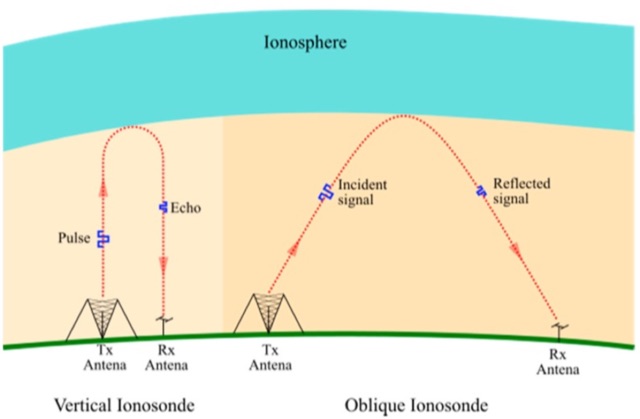 This document illustrates the processes carried out for the construction of an ionospheric sensor or ionosonde, from a universal software radio peripheral (USRP), and its programming using GNU-Radio and MATLAB.
 -
 This PDF document provides detailed information on the design, construction, and tuning of trapped vertical antennas with radials for ham radio operators. It covers the theory behind trapped antennas, practical considerations for installation, and tips for optimizing performance. Whether you are a beginner looking to build your first HF antenna or an experienced operator seeking to improve your station setup, this guide offers valuable insights and instructions. By understanding the principles outlined in this document, hams can enhance their operating experience and make the most of their radio communication capabilities.
 -
 Learn how to build a portable receiving antenna for the 160 meter band. This guide provides detailed instructions on constructing a loop antenna using a coaxial cable RG-316 with SMA connectors. The antenna weighs 1.7 kg and has dimensions of 2m in height and 1.892m in width. The wooden frame consists of four 0.945m long pieces and two 1m long pieces. Perfect for hams looking to enhance their 160m band reception during travel or portable operations.
 -
 The Slim Jim VHF antenna, originally designed by G2BCX, is a folded half-wave dipole fed by a quarter-wave matching section. This version, built from a recycled professional aluminum dipole, demonstrates that various materials—such as copper, brass, or twin-lead—can be used. The article details the antenna’s construction, required materials, and tuning process, emphasizing mechanical stability and ease of assembly. With proper adjustment of the feed point, it provides excellent SWR across the band. Its durability and simplicity make it a practical and efficient VHF antenna solution.
 -
 The article offers practical guidance for setting up Field Day antennas, emphasizing the unpredictability and need for quick adaptations. It provides a comprehensive table of wire lengths for various bands and antenna types, using 1mm bare wire, in both metric and Imperial units. The author highlights the benefits of this table in saving time and reducing errors. While acknowledging potential variations due to construction and environmental factors, the article presents the table as a reliable starting point, with plans for future updates to include more bands and antenna types. This resource is valuable for ensuring efficient and accurate antenna setup during Field Day events.
 -
 This article details the author's process of designing and building a trap dipole antenna for the 17, 12, and 6-meter amateur radio bands using a Yaesu FT-450 transceiver. The antenna incorporates parallel-tuned circuit traps to enable operation across multiple bands without switching aerials. Key construction details, including coil and capacitor specifications, are discussed, along with the testing results, which include successful long-distance communications on the 50 MHz band. The article highlights the flexibility of home-built antennas and provides insights for amateur radio enthusiasts looking to optimize multi-band performance.
 -
 This page provides construction details for a 4-element 10-meter Yagi antenna with 28 Ohm impedance. It includes information on the elements, positions, diagrams, and data related to frequency, gain, front-to-rear ratio, radiation resistance, SWR, and loss. The content is aimed at hams or radio operators interested in building and optimizing Yagi antennas for the 10-meter band.
 -
 The article describes a high-gain, compact beam antenna design for the 2-meter band (144-146 MHz). The NSH 4x4 Boomer is a 4-element antenna that is mounted on a 4-foot boom with an 8.2 dB gain, 1.2:1 SWR, and a front-to-back ratio of 18 db. It is designed for mobile operations and little area, making it perfect for field usage such as disaster management. The design employs regularly spaced parts with a straightforward gamma match for tuning, and the construction materials include a square boom and polished aluminum tubes. In local and portable tests, the antenna worked regularly, achieving contact distances of up to 15 kilometers.
 -
 Building an efficient antenna begins with selecting the right aluminum stock. This article provides a comprehensive guide to sourcing aluminum materials for antenna construction. It covers different aluminum grades, their tensile strengths, tempering options, and their suitability for various antenna components. The article also recommends reputable suppliers in the UK, making it a valuable resource for antenna builders seeking durable and high-performance materials.
 -
 This blog post documents the author's journey building an APRS micromodem for amateur radio applications. Using an open-source design by LY2EN, the author assembled a cost-effective Terminal Node Controller (TNC) with SMD components, an Arduino Nano, and a JDY-31 Bluetooth module. The construction process included PCB fabrication, careful component soldering, microcontroller programming, and Bluetooth configuration. A custom 3D-printed case protected the completed device. Field testing in Romania showed the device functioned with a Baofeng UV-5R radio, though antenna limitations affected performance. The entire project demonstrates an affordable DIY alternative to commercial APRS trackers.
 -
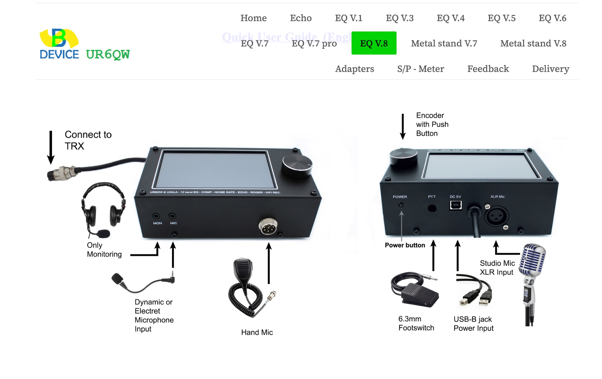 UR6QW offers special devices for ham radio operators, including PCBs and complete constructions in metal housing. Audio Equalizer, Echo boards, Metal stands. They provide pinouts for many transceiver models and can accommodate special orders upon request. The website also mentions the availability of sending parcels via DHL from their German office for European countries. Visit UR6QW for detailed information and sign up for free now.
 -
 This comprehensive three-part guide examines baluns (balanced-to-unbalanced devices) and their critical role in ham radio antenna systems. The author explains how baluns prevent common-mode currents on feedlines, which can distort radiation patterns and cause unwanted RF in the shack. Various balun types are analyzed, including coiled coax chokes, ferrite-core designs (W2DU), and toroidal-wound versions (Guanella/Ruthroff). Construction techniques for 1:1, 4:1, 6:1, and 9:1 current baluns are provided with practical guidance on wire selection, winding methods, and ferrite core properties. The article emphasizes that proper balun implementation is essential for optimal antenna performance, especially with directional arrays.
 -
 An **Arduino LC Meter** provides an accessible solution for precisely measuring inductance and capacitance values, crucial for RF circuit design, filter tuning, and troubleshooting in amateur radio applications. This project details the construction of a low-cost, accurate instrument using readily available components, making it an attractive alternative to commercial units for hams and electronics enthusiasts. The build process involves assembling a resonant circuit, integrating an Arduino microcontroller for frequency measurement, and displaying results on an LCD. Key components include an Arduino Uno, a 16x2 LCD, a 74HC14 Schmitt trigger inverter, and a few passive components. The design leverages the Arduino's processing power to calculate L and C values from resonant frequency shifts. Calibration procedures are outlined to ensure measurement accuracy, which is vital for critical RF work. The project includes schematics, a parts list, and the necessary Arduino code, enabling hams to construct a functional LC meter for their workbench.
 -
 This project details the design and construction of a Spider Quad antenna for HF bands (20m, 17m, 15m, 12m, and 10m). The boomless structure optimizes driver and reflector spacing, enhancing performance. Tuning and impedance matching were refined using antenna analyzers and a 1:2 balun. Final tests confirmed excellent SWR and gain, making this an efficient solution for top performance DXing.
 -
 This project describes the construction of a W3HH (T2FD) antenna for HF bands (3-30 MHz). While less efficient than a tuned dipole, it offers broad frequency coverage with a maximum SWR of 3.4 and reduces QRM (noise) significantly. On the 80-meter band, it shows slightly weaker signals than a dipole but with improved signal-to-noise ratio. The design includes non-inductive resistors, a 13:1 balun, and a "frog ladder" transmission line. Though not a high-performance antenna, it is compact and versatile, making it ideal for wide-band HF communication. Article in French
 -
 The Dipole Bazooka Antenna for 40 meters is a popular choice among amateur radio operators. Its design allows for easy construction using materials like RG58 coaxial cable and PVC. Measurements are calculated using specific formulas; for instance, at a frequency of 7,100 MHz, the total length is approximately 19.74 meters. This antenna offers a performance range of 97% to 99%, with an impedance of 49 to 52 ohms. Additionally, it can handle up to 1 kW of power and requires no modifications for connection.
 -
 This article details the design and construction of a compact 20-meter QRP SSB transceiver by Pete Juliano, N6QW, measuring just 2 x 4 x 2 inches—small enough for a shirt pocket. Inspired by a 1963 QST design and refined from a prior version, it employs bilateral circuits, a 4.9152 MHz homebrew crystal filter, switched-crystal VXO for 60 kHz coverage (14.160-14.220 MHz), and standard components like ADE-1L mixers and IRF510 PA for 1W output. Key innovations include a double-sided PCB skeletal frame for shielding and isolation, Vectorboard sub-assemblies, and ultra-miniature relays. The bilateral receiver/transmitter shares stages, omitting AGC for simplicity, while a W3NQN LPF and optional 10W external amp enable DX contacts. Tune-up focuses on crystal matching and bias for linearity. Videos on YouTube demonstrate performance, confirming excellent stability and audio. Total cost nears $100, prioritizing portability over features like CW.
 -
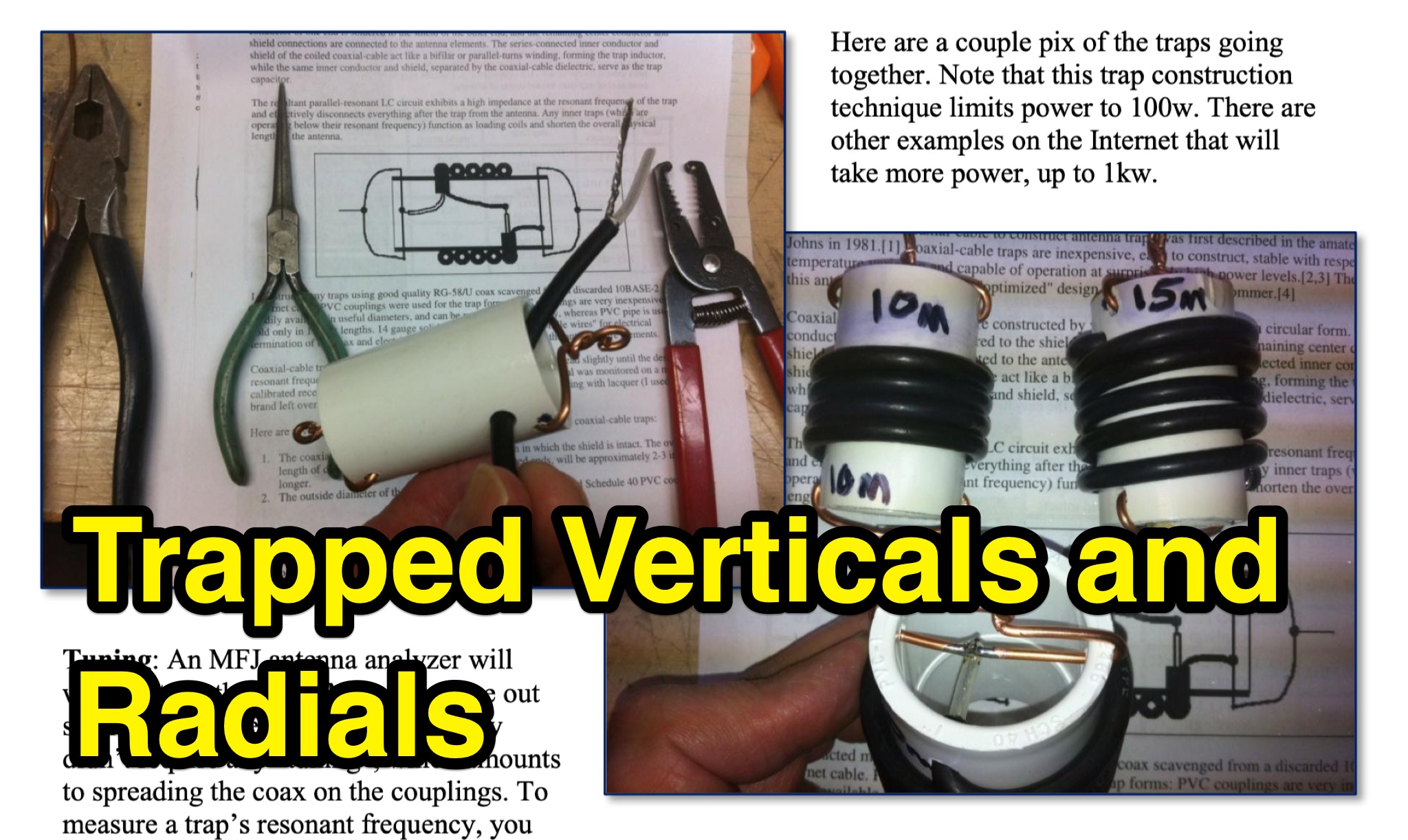
 EA4EOZ details the construction and testing of 50 MHz traps, a critical component for multiband antenna designs. The project addresses the challenge of sourcing high-voltage capacitors suitable for trap applications, exploring alternatives to expensive doorknob capacitors. The author successfully fabricated a capacitor using 1.6mm double-sided FR-4 PCB material, achieving a capacitance density of **2.6 pF/cm2**. Utilizing the _VE6YP calculator_, specific L and C values of 30 pF and 0.31 uH were determined for a 2cm diameter coil. Both the FR-4 PCB trap and a coaxial cable trap, constructed from _RG-58_, were built and tuned to approximately 50 MHz using a spectrum analyzer. The coaxial cable trap demonstrated superior performance, exhibiting a notch nearly **20dB deeper** than the FR-4 version. This practical comparison provides insights into trap construction for experimental antennas, with the coaxial cable trap selected for an antenna project intended for operation at up to 100 watts.
 -
 Explore the design and testing of a cage dipole antenna for 6 meters. Through innovative construction, witness a remarkable 77% increase in bandwidth and improved impedance characteristics.
 -
 Learn how to design a Hentenna antenna, a portable asymmetrical double-loop antenna ideal for amateur HF or VHF bands. This page provides details on constructing and optimizing the antenna for maximum performance in DX communications. Discover how altering the antenna's vertical feed section can adjust the VSWR resonant frequency and how changing the support pole's position can alter the beam direction. Originally developed by Japanese 6-meter operators, the 'Hentenna' offers a unique design that allows for horizontal polarization when vertically oriented. Explore radiation patterns, VSWR charts, and antenna currents diagrams to optimize your antenna's performance for long-distance contacts.
 -
 The All-Copper J-Pole Antenna Construction for 2 Meters document outlines a specific build methodology for a VHF base station antenna. It addresses common issues like dissimilar metal corrosion and feed line degradation often encountered with aluminum J-Pole designs, proposing an all-copper and brass solution with soldered connections for enhanced durability and electrical performance. This resource provides a comprehensive parts list in Table 1, detailing precise copper tubing lengths and other necessary hardware components. The design emphasizes DC grounding, which eliminates the need for insulating materials and simplifies installation, contributing to a robust and weather-resistant structure. Michael P. Hood, KD8JB, details an assembly process estimated to take approximately one hour, with total material costs projected under $15. The antenna's construction focuses on rigid copper tubing and fittings, ensuring long-term integrity for 144 MHz operation.
 -
 Learn how an experienced ham radio operator rebuilt his trap dipole antenna for 30, 40, and 80 meters after a storm damage. Discover the process of upgrading to a short trap dipole for 40, 80, and 160 meters using double-wound traps made from RG-58 coax. Follow along for construction details and tips on building this unique classi.
 -
 Delta loop antennas, particularly the 30 meter variant, offer unique advantages in terms of vertical polarization and omni-directional coverage. The construction process detailed by VE3VN highlights common mechanical and electrical challenges faced by amateur radio operators. Key design considerations include minimizing interaction with existing contest band antennas, achieving low elevation angles for DX chasing, and ensuring the antenna remains off the ground for agricultural clearance. The article provides specific measurements, such as the loop's height and feed point impedance, which are critical for optimizing performance. The use of NEC modeling software illustrates the importance of accurate resonance calculations, revealing how proximity to the tower affects both pattern and impedance. This practical account serves as a resource for hams looking to build effective antennas while navigating typical construction hurdles.
 -
 Learn how to construct a balanced Antenna Tuning Unit (ATU) for your ham radio equipment. Follow the instructions provided by Bengt, SM6APQ, to create a variable capacitor insulated from the ground for additional safety. Discover how to set up the ATU for the 20 to 10m band with proper spacing between coils. Use low power when adjusting the ATU for lowest SWR. Avoid using switches and opt for banana plugs for flexible connections. Visit the Creative Science Centre website for more information and resources on ATU construction.
 -
 This document outlines the construction of a homebrew Buddipole antenna variant, designed for portable use and emergency services. The antenna utilizes telescoping whips and loading coils, enhancing its versatility across various HF bands. Key components include fiberglass rods, brass fittings, and Anderson Power Pole connectors, ensuring robust electrical connections. The design emphasizes non-inductive materials to minimize interference, while practical assembly techniques, such as epoxy and heat shrink tubing, are employed for durability. This variant aims to improve upon traditional Buddipole designs, offering greater strength and functionality.
 -
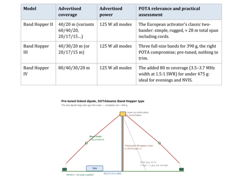 The resource discusses antenna families frequently utilized by _Parks On The Air_ (POTA) activators, focusing on the specific requirements for portable operations. It highlights the need for lightweight construction, rapid deployment, and sufficient efficiency to achieve the minimum **ten contacts** required for activation. The guide addresses adaptability to diverse field conditions, including the presence or absence of trees and varying ground surfaces. For each antenna type, the article provides a principle diagram, outlines its operational strengths, and details its inherent limitations. It also includes external links to practical field experiences, offering real-world context for each design. The POTA program, which involves setting up a complete station in a park, often within **thirty minutes**, underscores the antenna's critical role in successful activations.
 -
 Demonstrates the construction and portable deployment of a 40-meter horizontal loop antenna, often referred to as a "Sky Loop" or "DX-Buster." The design adapts a full-wavelength horizontal loop for field use, eliminating the need for traditional insulators by employing four 5-meter heavy-duty _squid poles_ and metal post bases for support. This setup facilitates rapid assembly, crucial for portable operations, with the antenna wire length specified at approximately 43-45 meters for optimal 40-meter band performance. The resource details the specific construction methodology, including winding the antenna wire around rubber caps on the squid poles and securing it with electrical tape. It provides a parts list and assembly techniques, focusing on minimizing components for ease of transport and quick setup. The article, originally published in the February 2013 edition of the Central Coast ARC "Smoke Signals" magazine, reflects practical experience. This documentation offers a field-deployable 40-meter loop antenna solution, utilizing readily available components like fiberglass squid poles. It presents a practical approach for operators seeking a robust, portable antenna for the 40-meter band, emphasizing simplicity and efficiency in its design and deployment.
 -
 The 1/4 wavelength vertical antenna project, initially designed for 20 meters, has evolved into a versatile portable solution covering 10 through 60 meters. K0BXB details its construction, emphasizing a bottom-loaded design with a tapped loading coil and four 10-foot counterpoise wires. The author shares personal experiences and field results, including **18 QSOs** during a park activation on 17m and 30m with 10 watts, and a **2,435-mile** contact with a contest station in Bonaire on 20m using 5 watts. Comparisons are drawn to commercial offerings like the _Wolf River Coils TIA_ and _QRPGuys Triband Vertical_, highlighting the DIY antenna's small footprint, light weight, and ease of tuning for POTA activations. The resource includes insights into using test equipment such as the _NanoVNA_ for SWR optimization and discusses various radiator lengths, from 17-foot wire to a 102-inch whip, demonstrating adaptability for different portable setups. Construction tips cover coil winding, tap placement, and connecting feedlines and radials using common components.
 -
 Ferrite E-cores offer a practical solution for constructing baluns, especially when connectors are already mounted on cables. These cores, commonly used in mass-produced pulse transformers, allow for multiple turns without dismounting connectors, making them ideal for control and power supply cables. The material of E-cores is generally suitable for common mode baluns up to 15 MHz, providing a cost-effective option for amateur radio operators. E-cores can often be sourced from old switch-mode power supplies, adding to their appeal for those looking to utilize existing resources. A notable example involves a balun on a USB cable using a Ferroxcube E 32x16x9, 3F3 core with four turns, secured by three cable ties. This setup demonstrates the ease of construction and stability achievable with E-cores. Another example features a balun with eight turns of shielded cable with RCA connectors on the same core, achieving 140 uH inductance at low frequencies. The impedance plot for this configuration is measured between the shield ends, illustrating the effectiveness of E-cores in practical applications. The article includes detailed figures and descriptions, providing valuable insights into the construction and application of baluns using ferrite E-cores. These examples serve as a guide for amateur radio enthusiasts looking to enhance their setups with cost-effective and efficient solutions.