Beacon keyers
Beacon Keyers
Sort:
Related Categories
-
 The page is about the 144 Mhz Dirty Beacon project, a VHF beacon keyer by 9A4QV. It provides technical information, project details, and resources for amateur radio operators interested in beacon keyers. The content is useful for those looking to build or learn about VHF beacon keyers.
 -
 A home made QRSS beacon project for the 10 MHz by VK2ZAY
 -
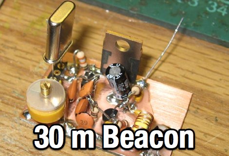
 A borderline insane 30m QRSS beacon project, completely independent of computer control and containing NO microprocessors!
 -
 10MHz WSPR and QRSS Transmitter Project
 -
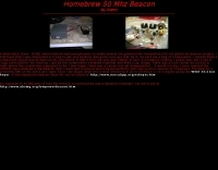
 30 Watt 50 MHz ham radio beacon de N6CA
 -
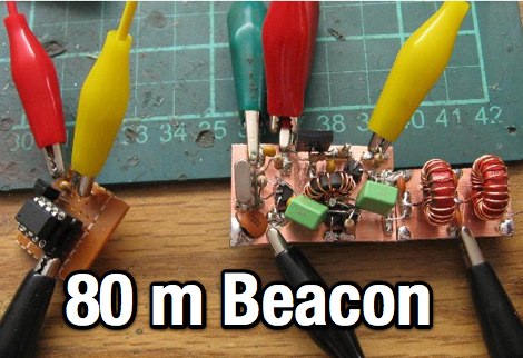 An home made CW beacon transmitter project running 1.5 W on the 80 meters band
 -
 A vertical antenna specifically designed to work with the 80 meter CW beacon keyer
 -
 Designing a beacon keyer that transmit the relative output power along to call sign.
 -
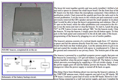 How to build a beacon keyer for 28 MHz using an old CB Radio transceiver, by Tom Sevart
 -
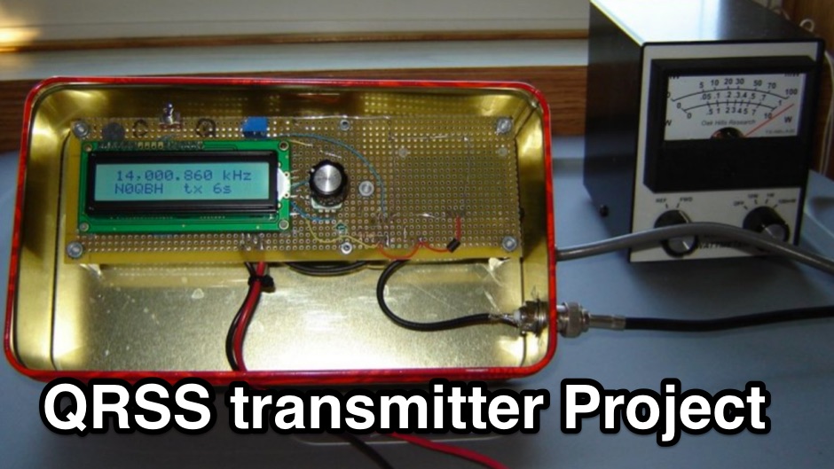 The N0QBH QRSS project page, a couple of projects using available kits for improved frequency and timing stability. A configurable DDS VFO 100mW transmitter with LCD display and a modified Hans Sommers 40m 100mW transmitter
 -
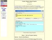 A small program to simplify changing messages in the Expanded Spectrum Systems Freakin' Beacon controller. The program makes it easy to modify an existing message or to have multiple messages available in different files ready to program into the beacon controller.
 -
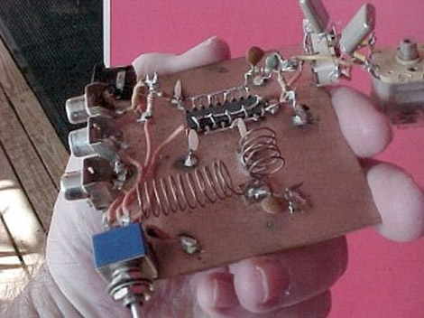
 This simple 30m QRSS beacon is built entirely out of junkbox parts, the only component purchased specifically for this project was the 10,140kHz crystal.
 -
 DIY beacon for six meters band by K9MU
 -
 10 meter propigation beacon project
 -
 IV3GFN beacon for six meters band
 -
 This circuit stores a single morse code message as bits in an EPROM chip, the message is sent to a relay which can key a CW transmitter.
 -
 N7KSB used this 1/2 watt CW transmitter, with a roof-mounted ground-plane antenna to work all continents and over 30 countries
 -
 As used on the new GB3VHF 144.43MHz Beacon
 -
 The next generation beacon platform for the OZ7IGY beacons should encompass both the analog and digital mode, i.e. FSK and MGM in a mixed mode configuration
 -
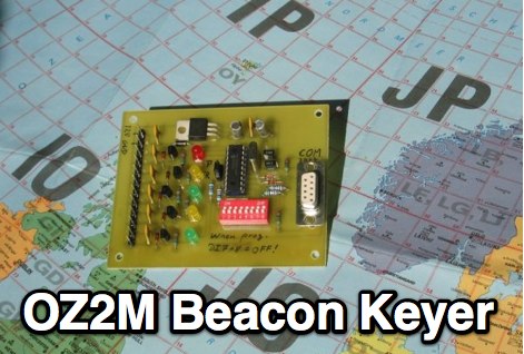 Circuit and software to build a beacon keyer, includes downloadable packages.
 -
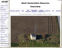 Next Generation Beacon hardware platform encompasses both analog and digital modes, i.e. CW FSK and MGM in a mixed mode configuration. The advantage of the mixed mode is that humans can decode the CW FSK by ear and the MGM can be decoded by computers way below what is audible. Therefore the MGM can be used for pre-human-conditions or early warning monitoring.
 -
 A Picaxe Morse Code keyer project with source code and links to useful resources by K6ACJ
 -
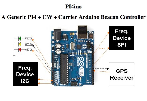 Generic PI4 + CW + Carrier Arduino Beacon Controller with interfacing to Analog Devices AD9833 DDS AD9850 DDS, AD9851 DDS, AD9912 DDS , AD9913 DDS, ADF4350 and ADF4351 synthesizers, ADF5355 synthesizer, ADF5356 synthesizer, Radio modulated by an audio soft-DDS Reverse DDS, RDDS microwave unit, Silicon Labs Si5351A programmable clock generator, Silicon Labs Si570 programmable XO/VCXO, Texas Instruments LMX2541 synthesizer
 -
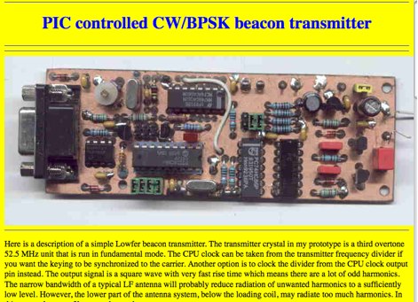 A description of a simple Lowfer beacon transmitter.
 -
 CW/QRSS beacon, based on a microcontroller PIC16F84, by Microchip, with only few other components. Schematic and component list available
 -
 Here is a simple, self-contained beacon which can run a few milliwatts or as much as a watt depending on choice of amplifier and supply voltage.
 -
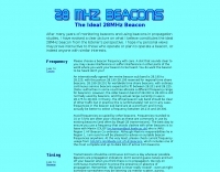 What constitutes the ideal 28MHz beacon from the listener's perspective by G0AEV
 -
 This page describes an cheap RF signal source, a portable micro beacon, using a low cost temperature controlled crystal oscillator
 -
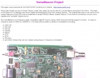 The VersaBeacon is a frequency agile, modulation agile RF source using a DDS chip and minimal support circuitry. It covers a frequency span of 1MHz to 150MHz in 1 Hz steps and provides a variety of modulations
 -
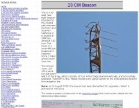
 A detailed construction guide for a 23cm (1296 MHz) beacon by W6PQL, featuring a PIC 16F628A microcontroller for CW/FSK keying, frequency multiplication, and a
 -
 10 meter 28.286 mhz 100 milliwatt Beacon
 -
 A simple QRSS beacon exciter for the 2200m amateur band, designed for weak signal operation using a single chip solution.
 -
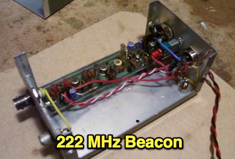 A CW beacon keyer for 222 MHz by VA3NFA
 -
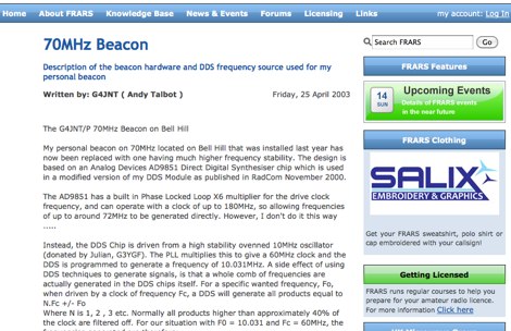 Description of the beacon hardware and DDS frequency source used for G4JNT personal beacon
 -
 A multi-mode QRP radio beacon built around the Arduino. This radio propagation beacon transmitter project is presented by M0XPD
 -
 This is a 30-watt sea level beacon intended for the coastal path between Northern and Southern California
 -
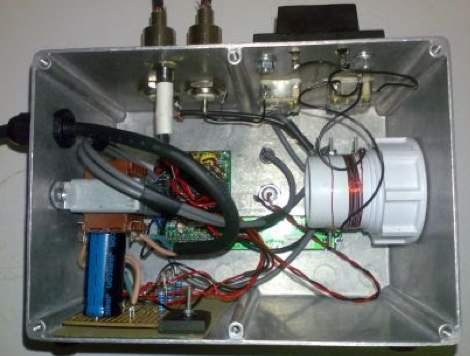
 The project aims to create a remote control system for the VK5RSE beacons located near Millicent, South Australia. The beacons on 144.550, 432.550, and 1296.550 MHz can interfere with nearby amateur radio operations, particularly for EME work on 1296 MHz. The remote control system uses a DTMF decoder and PIC microcontroller to allow turning the beacons on and off individually or in combination. The system is housed in a diecast box and powered from 5-8V. The password-protected control allows authorized users to manage the beacon operations remotely, helping mitigate interference issues for local amateurs.
 -
 CW Beacon kit by Expanded Spectrum Systems
 -
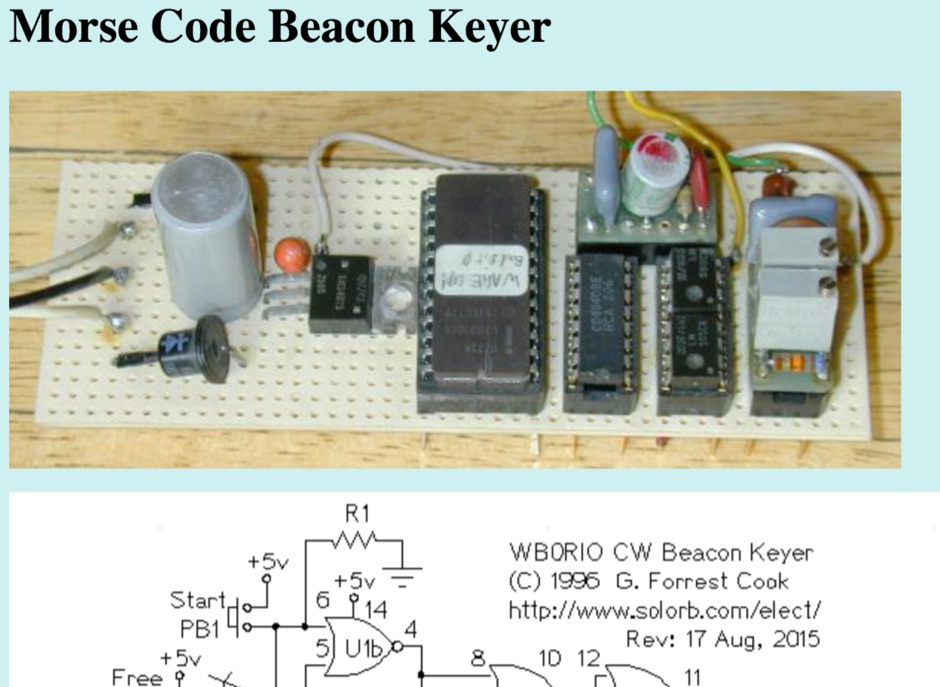 This circuit stores a morse code message as bits in an EPROM chip, the message controls a relay that keys a CW morse code transmitter. An Arduino processor can also be used in place of this circuit, that eliminates the need to build the circuit and program an EPROM.
 -
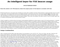
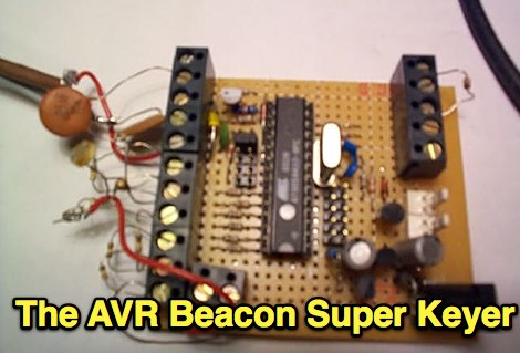 Description of an HF beacon keyer with telemetry. What makes the keyer rather different is its versatility - it is a multi-mode unit, with ASK and FSK modulation, sending Feld-Hell and Morse on command
 -
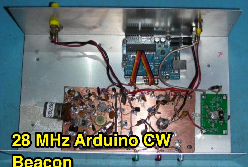 This project involves the construction of a 5 Watt Morse code beacon transmitter that operates in the 28.200 to 28.300 section of the 10 Meter Amateur Radio band. The beacon controller uses an Arduino Uno microprocessor board to produce the three signals that control the transmitter.
 -
 This document details the construction, programming, and operation of a modular WSPR transmitter. The transmitter utilizes an ESP8266 NodeMCU, an SI5351 synthesizer with a TCXO for stability, and selectable low pass filters. Construction involves soldering headers, components, and assembling filter module. The ESP8266 is programmed via the Arduino IDE, requiring library installations and code modifications, including network credentials, callsign, and frequency . The transmitter is powered by USB or Vin terminals and its frequency is selected by jumpers and software settings. The document also covers FCC restrictions and how to use the WSPR network