Search results
Query: signal
Links: 731 | Categories: 52
Categories
- Technical Reference > RF Signal Generators
- Manufacturers > Test Equipment > Signal generator
- Software > Signal Generator
- Technical Reference > Test Equipment > Signal Generator
- Software > Weak Signal
- Operating Modes > Weak Signal
- Shortwave Radio > Broadcasters > Time Signal Radios
- Antennas > Active
- Technical Reference > AI Ham Radio
- Operating Modes > Aircraft scatter
- Operating Modes > Amateur Television
- DX Resources > Beacons > Beacon Monitoring
- Antennas > Collinear
- Software > Decoders
- Operating Modes > Satellites > Digital Satellites
- Software > Digital SSTV
- Software > DRM
- Operating Modes > DSP
- Software > DSP
- Technical Reference > Filters
- Operating Modes > FT8
- Radio Equipment > HF YAGI Antennas
- Antennas > Theory > Impedance matching
- Software > JT65
- Operating Modes > JT65
- Operating Modes > JT9
- Technical Reference > Key Clicks
- Antennas > Lindenblad
- Propagation > Long-Delayed Echoes
- Radio Scanning > Nature
-
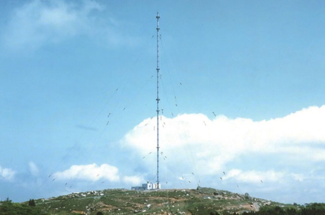
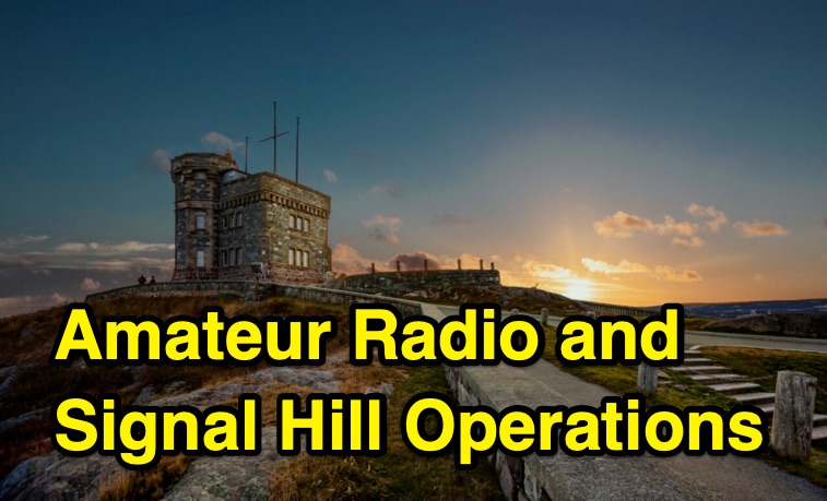 Examines the historical context of amateur radio, specifically focusing on Guglielmo Marconi's pioneering wireless transatlantic signal reception at Signal Hill, Newfoundland, in 1901. It describes the operation of a contemporary remote radio station at Signal Hill, utilizing the special event call sign _VD1M_ issued by Innovation, Science and Economic Development Canada. The content recounts a specific contact from Signal Hill, reporting a signal strength of 5 by 9 to a station in Sarnia, Ontario, which received the signal at 3 by 3. The narrative also introduces the concept of 'Marconi chasers' who endeavor to replicate historical transmission methods. Further, the resource discusses general amateur radio operating procedures, the evolution of the hobby, and its critical role in emergency communications, citing examples from hurricanes _Irma_ and _Maria_ in 2017 and the conflict in Ukraine in 2022.
 -
 An Arduino-based interface provides a remote tuner call command for Icom **IC7700** and **IC7800** transceivers, addressing the lack of a built-in function for external tuners such as the MFJ 998RT. This setup initiates a low-power transmit signal, typically 15 watts, allowing the remote autotuner to perform its matching sequence. The article details the required CI-V line communication and modifications to existing Arduino code, specifically referencing contributions from Jean-Jacques ON7EQ for improved Icom interrogation routines. The system involves a sequence of steps: storing the transceiver's current mode and power, disabling the internal autotuner, activating a control relay to interrupt the amplifier line, switching to RTTY mode at low power, and initiating transmit. The transmit duration is manually controlled by the operator, observing the SWR meter until a low SWR is achieved, then a second button press stops the transmission. A built-in 4-second transmit limit provides a safety measure. After tuning, the routine restores the original mode and power settings, re-enables the internal autotuner, and performs a brief 2-second RTTY transmission for internal tuner adjustment. The circuit diagram includes a Panasonic form 2 relay for amp control and emphasizes critical delays in the Arduino code for stable operation at 9600 baud CI-V communication. Compatibility with logging software like DXLab, N1MM, and N3FJP is noted, with specific interrogation time settings required to avoid conflicts.
 -
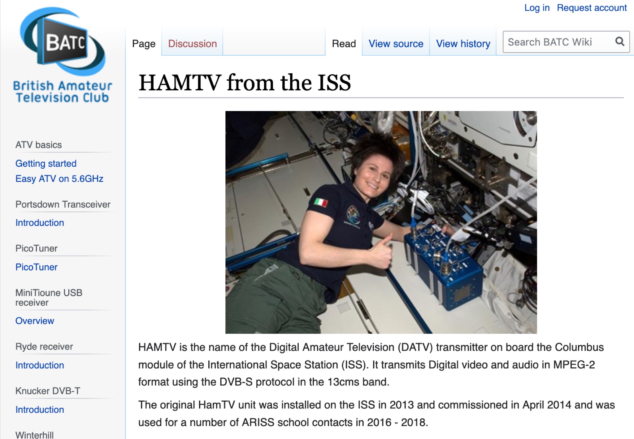 Learn about the HAMTV Digital Amateur Television (DATV) transmitter on the International Space Station (ISS), transmitting video and audio in MPEG-2 format using the DVB-S protocol. Discover its history, installations, failures, and repairs, as well as the current status and live video feed. Explore the technical details and challenges of the HAMTV transmitter, including power output, polarization, and antenna location. Find recordings of previous transmissions and understand the potential signal reflections caused by various ISS components. Stay updated on the latest developments and activities related to HAMTV from the ISS.
 -
 JJY is a time signal transmitter operated by the National Institute of Information and Communications Technology (NICT) in Japan. It broadcasts on two frequencies, 40 kHz and 60 kHz, and is used for time synchronization in Japan.
 -
 This resource presents a non-rigorous evaluation of the front-to-back (F/B) ratio of short Beverage antennas, specifically designed for low-band operation on frequencies such as 160, 80, 40, and 30 meters. The author, VE1ZAC, details the methodology used to measure the F/B ratio, which involves using a Millen Grid Dip Oscillator as a portable signal source. Measurements were taken by switching the antenna direction and recording S Meter and preamp readings to derive gain numbers. The document discusses the challenges faced in achieving accurate measurements and the assumptions made during the process, such as the calibration of S Meter units at 6 dB. This evaluation is particularly relevant for amateur radio operators interested in antenna performance on low bands.
 -
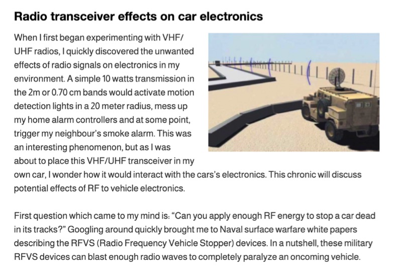 Illustrates the potential for radio frequency (RF) energy from amateur transceivers to interfere with vehicle electronics, drawing parallels to military _Radio Frequency Vehicle Stopper_ (RFVS) technology. The resource details personal experiences with VHF/UHF signals activating household devices and then pivots to the complexities of RF interaction with automotive systems, noting the development of multi-frequency RFVS (MFRFVS) to overcome vehicle-specific vulnerabilities. It highlights that while car manufacturers conduct RF immunity tests, the rigor varies, with luxury brands likely performing more extensive evaluations than others who merely meet minimal certification. The article explores practical considerations for mobile amateur radio installations, suggesting antenna placement over the car, using lower power output, and proper grounding to mitigate adverse effects. It acknowledges the lack of comprehensive data on RF/vehicle combinations but emphasizes that adherence to these basic principles can reduce risks. The author shares observations of unexplained car computer codes in a 2002 SUV, speculating on potential RF induction. Concerns are raised about the increasing complexity and interconnectedness of modern car electronics, including Bluetooth, remote access, and electronic control systems for critical functions like steering and braking. The article points out the diminishing space for third-party installations in contemporary vehicles and references the ARRL's stance on auto manufacturer policies regarding amateur radio installations, which generally advise against them.
 -
 The **Yaesu FRG-100** shortwave receiver, introduced in 1992, operates across a frequency range of 50 kHz to 30 MHz, accommodating AM, LSB, USB, and CW modes, with an optional narrow-band FM capability. Its physical dimensions are 238 x 93 x 243 mm, with a weight of 3 kg, making it suitable for both portable and fixed station deployments. Power options include standard mains voltage or 12VDC, providing operational flexibility for diverse listening environments. The front panel integrates a manual tuning knob, an analogue signal strength meter, and an LCD display that provides critical information such as frequency, operating mode, memory channel, and time. Users can configure various operational parameters, including tuning steps and bandwidth filters, to optimize reception for specific signals. This review highlights the FRG-100's straightforward interface and its utility for shortwave listening enthusiasts. The design emphasizes user-friendly adjustments for settings, which contributes to its appeal among those interested in general coverage reception.
 -
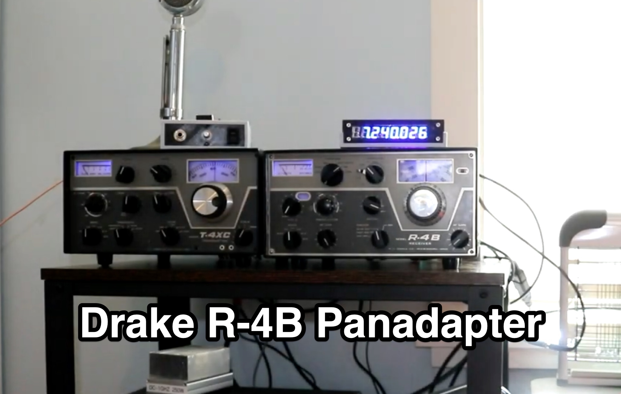 Learn how to enhance your Drake R-4B ham radio receiver by adding a panadapter. Follow along as the author shares their journey of becoming a ham radio operator and restoring vintage radios. Discover how a panadapter can help you visualize a wider frequency range, improving signal detection and communication. Whether you're a seasoned ham or just starting out, this guide provides valuable insights and practical tips for maximizing your radio experience.
 -
 This article describes a DIY RF field strength meter project inspired by VK3YE's "The Squeakie" design. The device, built around a 555 timer IC and a 1N4148 diode, converts RF signal strength into audible tones with proportional pitch. The author enhanced the original design by adding volume control, LED indication, and digital readout capabilities using an Arduino Nano and LCD display. The completed project functions as a versatile RF detection tool, suitable for antenna testing and fox hunting, while offering multiple output methods: audio, visual, and digital measurement display.
 -
 The Pressure Paddle V2.0 simplifies the original 2019 design by using MOSFETs’ unique properties for reliable, minimalistic switching. When pressure sensors detect a press, they reduce resistance, activating the MOSFET and lowering voltage until it stabilizes at the MOSFET’s threshold. This ensures consistent “key down†signals for the transceiver. Compatible with 3-5V logic systems, the circuit operates independently of pull-up resistor size. The PCB is lightweight, easy to assemble, and can be packaged in heat shrink or mounted. This version maintains durability with fewer components and flexible packaging options.
 -
 This online project documentation details the construction of a hands-free microphone interface unit designed for _mobile_ amateur radio operation. The curriculum covers the integration of electret microphone elements with amateur radio transceivers, specifically addressing **VHF** band communication. It outlines the circuitry for a switch box that provides an interface between various radio models and microphone types. The guide specifies the inclusion of a **1750 Hz** tone-burst generator for accessing amateur radio repeaters, an operational protocol for many VHF systems. Design considerations include the reduction of ambient vehicle noise through an adjustable audio input level control. The project provides schematics and wiring diagrams for connecting the interface unit to specific amateur radio transceivers, including the Yaesu FT-817. It addresses the selection and adaptation of readily available electret microphone and earpiece assemblies, initially sourced from mobile phone accessories, and later from dedicated headset units. The design incorporates a control mechanism for radio functions, enabling hands-free operation during _mobile_ excursions. Circuit details cover power supply considerations for the electret microphone and signal routing for both transmit audio and received audio monitoring. The documentation specifies component selection for the switch box, ensuring compatibility with common amateur radio microphone input impedances and output levels. This includes considerations for PTT line switching and audio path isolation. DXZone Focus: Online Project Documentation | Hands-Free Mobile Microphone Interface | Electret Microphone Integration | 1750 Hz Tone-Burst Generation
 -
 The article describes ongoing issues with a new TS590s transceiver, including intermittent reception and transmission failures. After a repair diagnosed as a "Control Unit interruption," the problem persisted. The author discovered the cause was a poorly crimped CN601 connector on the Control Unit board, leading to signal loss when moved. Soldering the connector resolved the issue. Similar problems reported by other users suggest a potential defect in the cables, pointing to a possible manufacturing issue.
 -
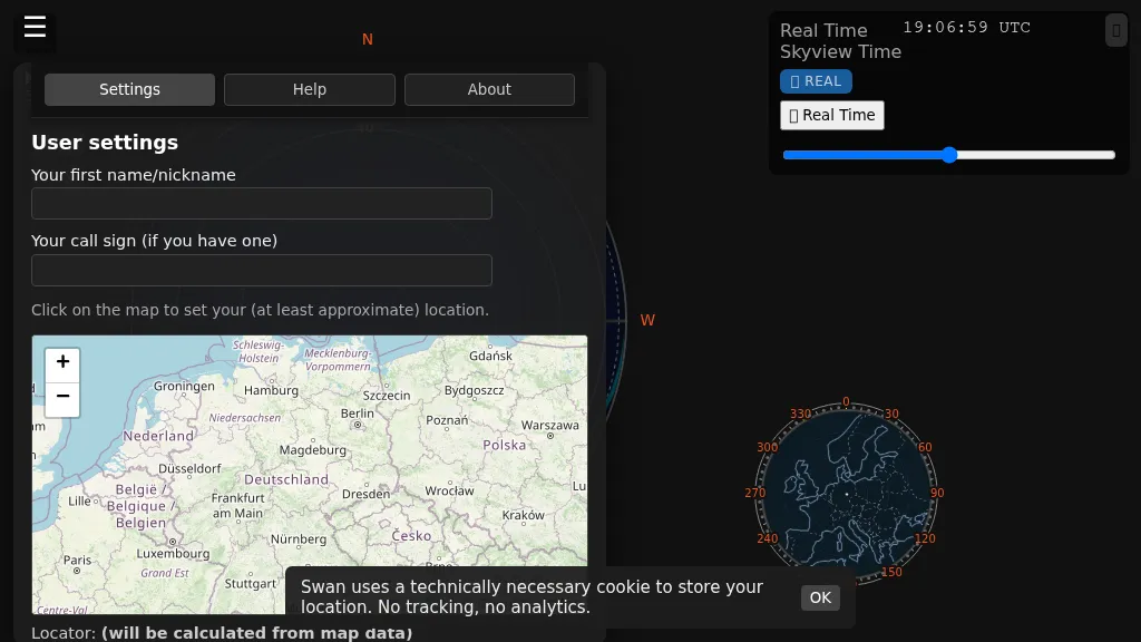 Swan provides a real-time, browser-based visualization of **meteor radiants** and forward scatter corridors, serving as a modern re-imagining of the classic Virgo meteor sky visualization tool. It displays meteor radiant and radio scatter geometry, offering both visual and numerical skyview data. The tool updates in real-time, showing current sky conditions and allowing users to pause and review specific timeframes for analysis of meteor shower activity and potential radio propagation paths. This enables operators to identify optimal windows for **meteor scatter** contacts. Operators can utilize Swan to predict and optimize their meteor scatter DX attempts by understanding the geometry between their station, meteor radiants, and potential receive stations. The interface presents critical data points for assessing forward scatter opportunities, which is crucial for maximizing short-duration meteor burst communications. By observing the real-time skyview, users can correlate meteor activity with observed signal enhancements, refining their operating strategies for specific meteor showers or random meteor pings.
 -
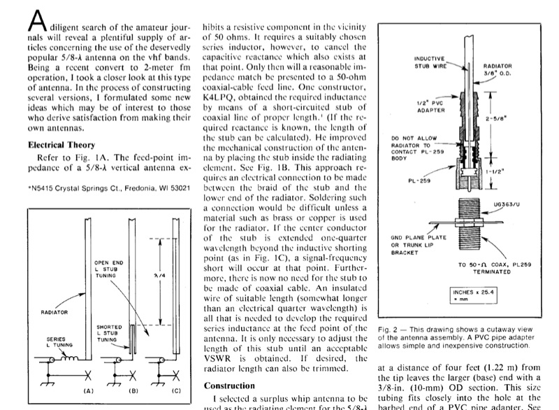 A 5/8-wavelength vertical antenna for 2-meter FM operation is detailed, focusing on eliminating loading coils by utilizing a series inductor to cancel capacitive reactance at the feed point, thereby presenting a 50-ohm impedance match. The design illustrates three basic configurations, including a method employing a short-circuited coaxial stub for inductance, as implemented by K4LPQ. An alternative design is presented where the center conductor of the stub is extended one-quarter wavelength, creating a signal-frequency short and allowing for an insulated wire stub to develop the required series inductance. The article provides electrical theory and mechanical considerations for building the antenna, emphasizing the adjustment of stub length for proper impedance matching. This technical documentation is intended for amateur radio operators interested in homebrewing VHF antennas, offering practical insights into impedance matching techniques for vertical radiators.
 -
 Tracing the foundational work of Guglielmo Marconi, this article details his early laboratory experiments in 1895, where he successfully transmitted wireless signals over 1.5 miles. It highlights his 1896 patent for a wireless telegraphy system in England and subsequent demonstrations, including signal transmissions up to 6.4 km (4 miles) on Salisbury Plain and nearly 14.5 km (9 miles) across the Bristol Channel. Marconi's work built upon the mathematical theories of _James Clerk Maxwell_ and the experimental results of _Heinrich Hertz_, proving the practical feasibility of radio communication. The resource further chronicles the formation of The Wireless Telegraph & Signal Company Limited in 1897 and Marconi's relentless efforts to popularize radiotelegraphy. A significant milestone was the 1901 transatlantic reception of the Morse code letter "S" from Poldhu, Cornwall, at St. John's, Newfoundland, using a kite-supported wire antenna, defying contemporary mathematical predictions about Earth's curvature limiting range. This achievement underscored the global potential of radio. The article also touches upon Marconi's later discoveries, such as the "daytime effect" concerning atmospheric reflection of radio waves, and his 1902 patent for a magnetic detector, which became a standard wireless receiver. His contributions earned him a Nobel Prize in 1909.
 -
 SAT filters ensure effective full-duplex satellite QSOs by mitigating interference between 145 MHz uplink and 435 MHz downlink signals. Custom coaxial and SMD-based filters address transmitter harmonic interference and improve receiver isolation, achieving over 70 dB suppression in the undesired band. Designed for simplicity, these filters maintain optimal VSWR and are housed in shielded brass enclosures. Practical implementations with Yagi antennas demonstrate compatibility with SDR systems, enabling seamless communication even in challenging satellite conditions, such as low-elevation passes and DX pile-ups.
 -
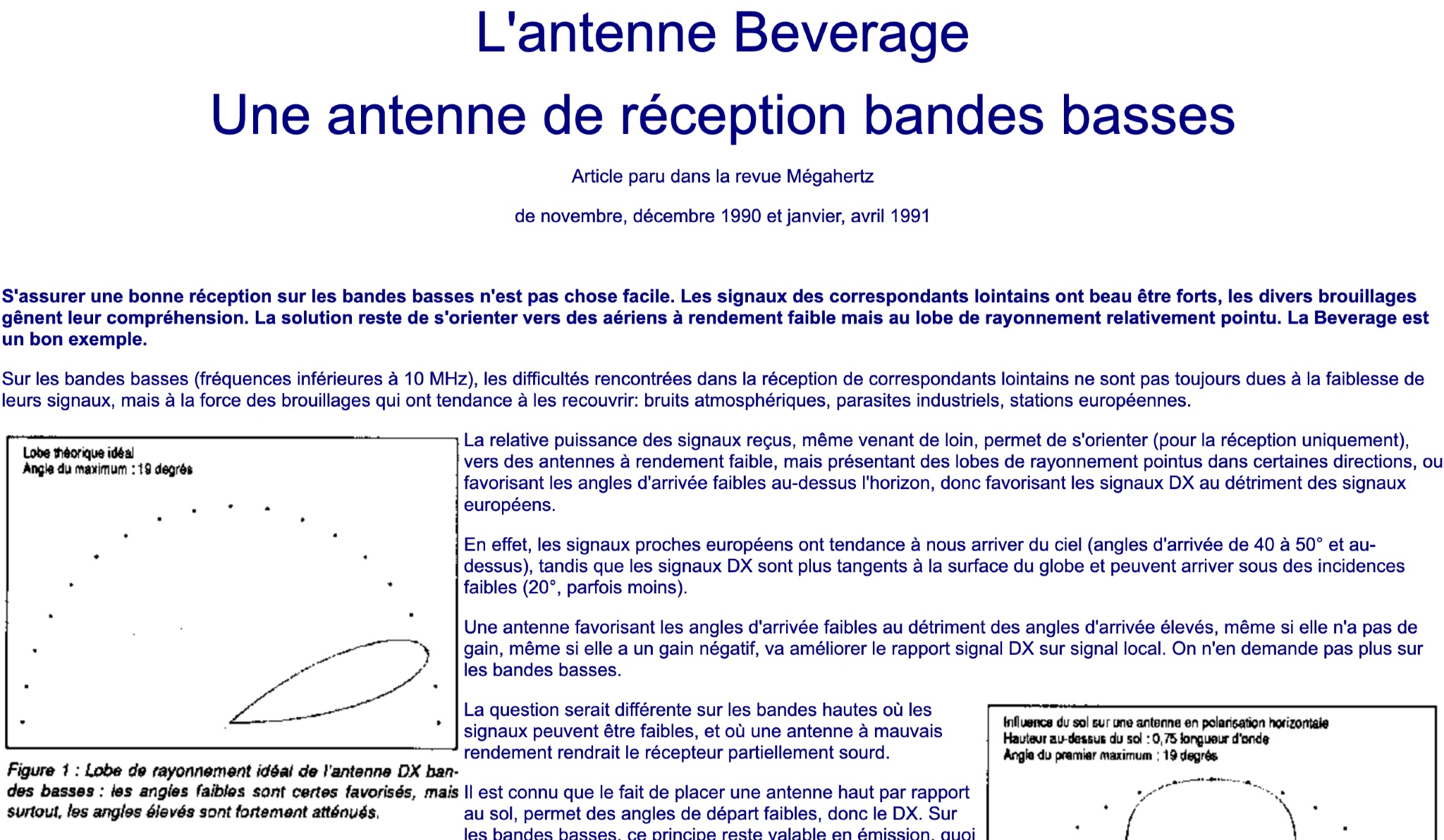 This article discusses the Beverage antenna, a reception antenna for low bands, originally published in the Megahertz magazine between November 1990 and April 1991. It explains the challenges faced in receiving signals on low bands due to interference and how the Beverage antenna's directional radiation pattern can help improve reception of distant stations. The article highlights the importance of choosing antennas with low efficiency but sharp radiation lobes for better DX signal reception. It also compares the reception characteristics of signals from European stations versus DX stations, emphasizing the benefits of antennas favoring low arrival angles for DX signals on low bands.
 -
 Early 20th-century transatlantic wireless communication efforts involved distinct technical approaches by Reginald Fessenden and Guglielmo Marconi. Marconi's systems, operational until approximately 1912, primarily utilized _spark technology_ for wireless telegraphy, facilitating Morse code communication between ships and across oceans. His Poldhu station in December 1901 radiated signals in the MF band around 850 kHz, later evolving to 272 kHz in October 1902, and eventually 45 kHz by late 1907 with increasingly larger antenna structures like the pyramidal monopole and capacitive top-loaded arrays. Fessenden, conversely, focused on _continuous wave transmission_ for wireless telephony, recognizing its necessity for speech. His transatlantic experiments in 1906 employed synchronous rotary-spark-gap transmitters and 420-foot umbrella top-loaded antennas at Brant Rock, MA, and Machrihanish, Scotland, tuned to approximately 80 kHz. Fessenden later utilized the _Alexanderson HF alternator_ at 75 kHz by late 1906 for pure CW transmission, integrating a carbon microphone for amplitude modulation. Receiver technology also differed, with Marconi initially relying on untuned coherer-type detectors, later developing the magnetic detector in 1902, while Fessenden's CW approach necessitated more advanced detection methods.
 -
 This study analyzes the antenna pattern of the Utah Amateur Radio Club's 146.760 MHz repeater following antenna relocation in 1997. Noting degraded transmission toward the north, a customized signal mapping system using a Yaesu FT-817, GPS, and software was developed to log real-time signal data. Calibration techniques extended the radio's signal range, enabling precise field measurements. The method allowed continuous signal strength monitoring while driving, revealing anomalies in coverage likely due to tower modifications. Findings helped assess and visualize the antenna’s actual radiation pattern and highlighted environmental impact on signal distribution.
 -
 Demonstrates the construction of an active loop converter specifically designed for the Low Frequency (LF) bands, addressing common localized noise interference in LF reception. The design integrates a sharply tuned circuit and a tuned loop antenna, utilizing the loop as the sole tuned inductive element. By applying positive feedback, the converter significantly increases the loop's effective Q, achieving factors between 1000 and 2000, which sharpens tuning and reduces noise. The circuit employs an _NE602_ mixer stage, feeding its output to an HF receiver, with a crystal-locked local oscillator at 4 MHz. A 20-turn, 0.8-meter square loop antenna with 500 uH inductance is detailed, connected via 2 meters of figure 8 flex cable. The converter offers three selectable frequency bands: 195-490 kHz, 150-220 kHz (including the New Zealand amateur band), and 128-160 kHz (covering the European amateur band). Performance measurements indicate an effective 3dB bandwidth of approximately 100 to 200 hertz at 200 kHz. The article provides insights into component selection, including an _LF353_ op-amp and a trifilar wound transformer on a ferrite core. Sensitivity figures are presented, showing 7.5 uV of converted output per 1 uV/meter signal strength into a 50-ohm load, or 37.5 uV into an _FRG7_ receiver, highlighting its capability to extract weak signals from noise.
 -
 The 4m Slim Jim antenna project provides a construction guide for a low-cost, high-performance aerial designed specifically for the 70 MHz FM band. This design achieves a 1:1 SWR across the 4m FM band with straightforward adjustment of the feed point, utilizing RG-58 coax. Its low angle of radiation contributes to effective signal propagation. Construction involves using plastic knitting needles as spreaders and a telescopic fishing pole for support, with components secured using two-part epoxy. Annealed bare single-core copper wire forms the radiating element. The setup process includes raising the antenna at least 3 meters above ground for tuning, adjusting the RG-58 feed point for optimal SWR, and then soldering connections. Waterproofing is achieved with yacht varnish. The design emphasizes low wind resistance for durability, making it suitable for exposed outdoor installations. A PDF construction diagram is available to supplement the written instructions.
 -
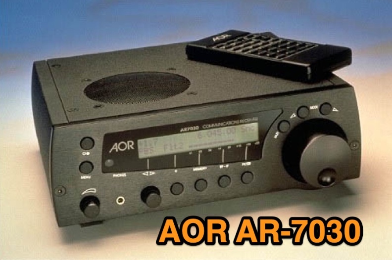 Examines the AOR AR-7030 communications receiver, detailing its technical specifications and operational characteristics. The resource describes its compact design, CNC machined aluminum cabinet, and a frequency range spanning 0-32 MHz. Key features include a ceramic metal cased 4 kHz AM filter, with typical bandwidths of 2.2 kHz, 4.0 kHz, 5.3 kHz, and 9.5 kHz, alongside 400 memory channels and multi-timer functionality. It emphasizes the receiver's high-quality components and a design philosophy focused on reliable performance without superfluous features, making it a dedicated tool for serious listeners. The review assesses the AR-7030's performance within its price class, particularly for **medium wave** and **shortwave** reception. It provides insights into how the receiver's design choices, such as its robust construction and specific filter options, translate into practical listening experiences. The analysis highlights its suitability for users prioritizing signal clarity and operational stability over extensive, complex features, offering a clear perspective on its utility for dedicated DXers and broadcast listeners.
 -
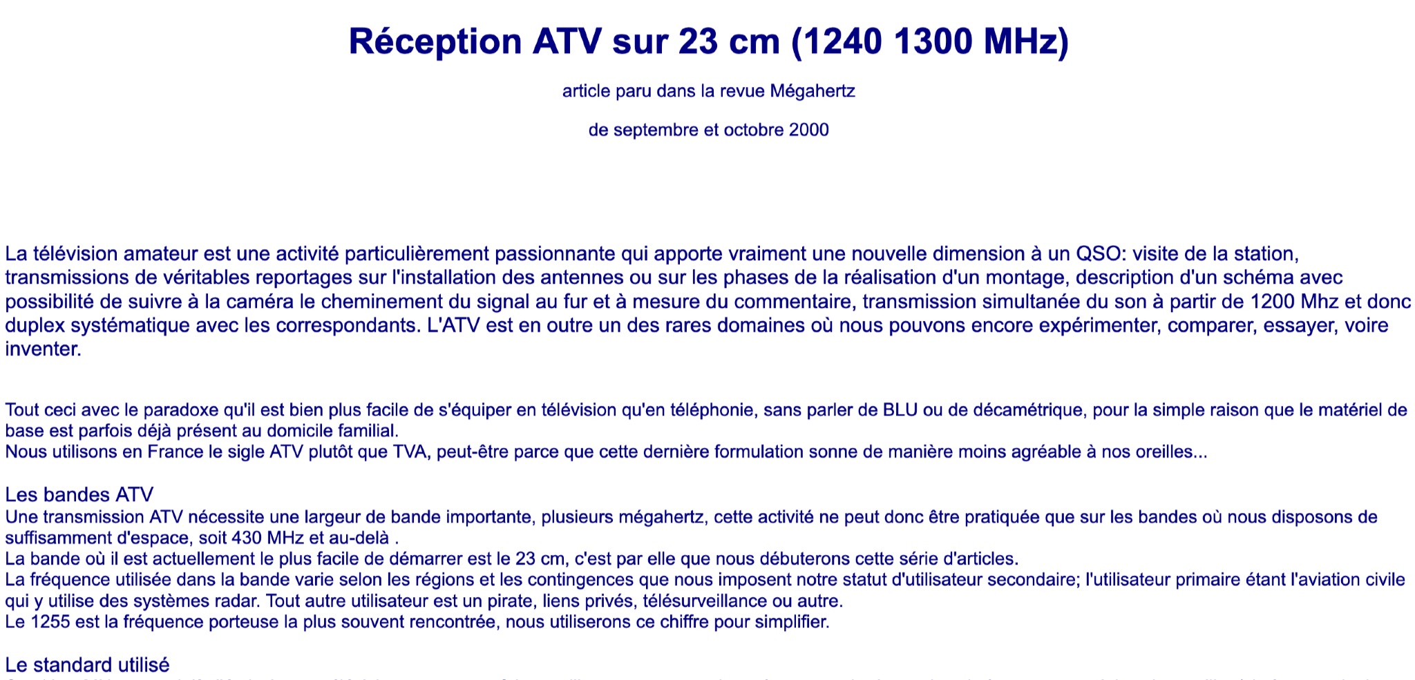 Learn about Amateur Television (ATV) on the 23 cm band (1240-1300 MHz) in this article from the September and October 2000 issue of Mégahertz magazine. Discover how ATV adds a new dimension to QSOs by allowing hams to visit stations, transmit real reports on antenna installations, follow signal paths on camera, and have simultaneous sound transmission. Explore the world of ATV experimentation, comparison, and innovation, made easier by existing equipment in many ham radio operators' homes. Find out about the ATV bands, bandwidth requirements, and the 23 cm band as a starting point for ATV activities.
 -
 Optimizing on-air audio for SSB, DXing, and contesting operations is addressed through a range of specialized audio processing equipment. The offerings include multi-band equalizers, specifically 5-band, 8-band, 10-band, and 12-band units, some integrated with features such as compressors, echo effects, noise gates, and phase rotation capabilities. These devices are engineered to interface with common amateur radio transceivers, with explicit compatibility noted for models like the Yaesu FT-DX10, FT-DX101D, FT-1000MP, FT-DX5000, Collins HF-380, and Flex 6300, alongside analog S/P meters for Icom rigs. The product line focuses on enhancing microphone audio characteristics, supporting XLR dynamic microphones for improved signal clarity and presence. The manufacturer, DB6QW Electronics, emphasizes direct support and a 100% manufacturer's warranty, reflecting confidence in product quality and operational reliability. This resource details specific audio processing tools designed to refine the transmitted audio signal, providing operators with granular control over their voice characteristics for competitive and casual amateur radio communications.
 -
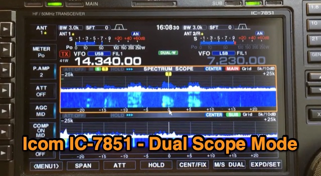 The Icom IC-7851 features the capability to display two scopes simultaneously, providing frequency, mode, and antenna information for each receiver. Users can choose between vertical or horizontal display orientations, and the dual scopes are also viewable on a high-resolution monitor connected to the radio. Additionally, the IC-7851 allows for mouse connectivity, enabling users to click on signals displayed on either scope for quick tuning. A demonstration video is available showcasing this dual scope functionality.
 -
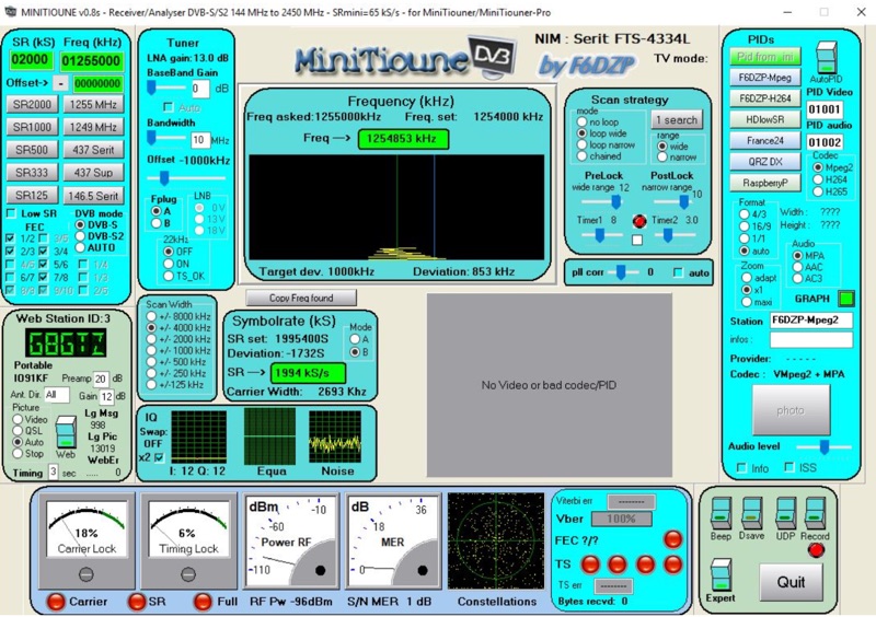 Receiving Digital Amateur Television (DATV) signals requires specialized software to interface with hardware tuners and decode the video stream. The _MiniTioune_ software, developed by F6DZP, serves this purpose, providing a Windows-based application for DVB-S and DVB-S2 reception and analysis. It is designed to work in conjunction with _MiniTiouner_ hardware, enabling hams to monitor DATV transmissions, including those from the QO-100 geostationary satellite. The resource outlines the initial setup process, including connecting the MiniTiouner hardware via a high-quality USB2 mini cable and running diagnostic test software. It details how to configure essential parameters such as symbol rate (SR), FEC rate, and DVB mode for various signal sources, from domestic satellite dishes to local DATV transmitters. Troubleshooting steps for common issues like "no video displayed" are also provided, often pointing to corrupted software filters or incorrect _Auto PID_ settings. Advanced features like the Web monitor for remote signal reporting and integration with _VLC_ media player for more tolerant decoding of non-DVB compliant signals are covered. The document also references a comprehensive user guide by W6HHC for the _MiniTiouner-Express_ system, which utilizes the same software, offering further in-depth assistance for operators.
 -
 This online construction guide details the assembly of a signal generator specifically for the **13cm band** (2.4 GHz). The curriculum focuses on the integration of a Voltage Controlled Oscillator (VCO), specifically the ROS-2400, to produce a stable RF signal. The resource outlines the necessary components for frequency generation and output, including the use of a Mini-Circuits MMIC amplifier for signal conditioning. The construction protocol involves configuring the ROS-2400 VCO to operate within the 2.3 GHz to 2.45 GHz range, ensuring frequency coverage for amateur radio _microwave experimentation_. The guide specifies the output power level, approximately 70mW, directly from the MMIC stage, indicating its application as a low-power instrumentation source rather than a transmit-capable device. This project provides a practical example of constructing a dedicated test instrument for microwave frequency measurements and system alignment on the **13cm band**. DXZone Focus: Construction Guide | 13cm Signal Generator | VCO Integration | Microwave Experimentation
 -
 Define the SWL contest 2026 as an event for monitoring a variety of languages on _medium wave_ (MW) and _shortwave_ (SW) AM radio stations. Participants can utilize either traditional radio receivers or _WEB SDR_ platforms to log their findings. The contest encourages the use of both analog and digital methods to maximize the diversity of languages captured. The contest rules specify that entries must include detailed logs of the stations received, including frequency, time, and language identified. Logs should be submitted in a standardized format to ensure consistency and accuracy in judging. The use of WEB SDR is particularly highlighted for its ability to access distant stations that may not be reachable with local equipment. The contest is open to all SWL enthusiasts worldwide, with a focus on European WEB SDR access. The event aims to foster a deeper understanding of global broadcasting patterns and linguistic diversity. Participants are encouraged to explore various bands within the MW and SW spectrum, enhancing their skills in signal identification and language recognition. The contest offers a unique opportunity to engage with the global SWL community and share insights into the art of listening.
 -
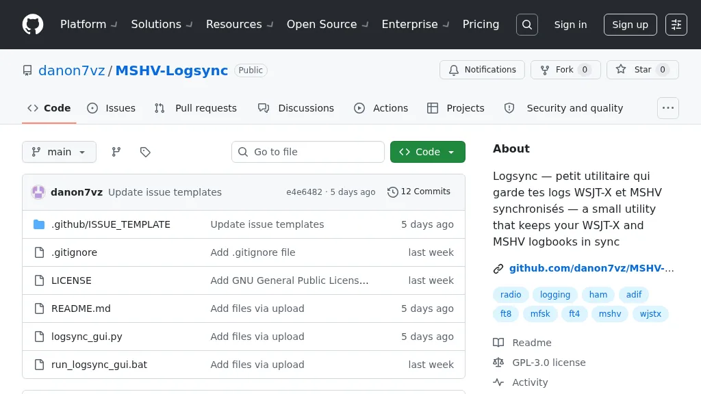 Manages log consistency across multiple digital mode applications, specifically addressing the common issue of log divergence between _MSHV_ and _WSJT-X_ for FT8, FT4, and other weak-signal modes. This prevents duplicate contacts and ensures accurate DX tracking when using both programs. The utility computes a deduplicated union of entries from both `_mshvlog.edim` and `_wsjtx.log` files, then updates each log with missing QSOs. It supports a deduplication key based on callsign, date, time (to the minute), band (derived from frequency), and mode. The tool is available as a standalone Windows executable or a Python version requiring Python 3 with _Tkinter_. Users select log folders, close both applications, and initiate the 'Merge' function. The process includes automatic timestamped backups of log files before any modifications, safeguarding QSO data.
 -
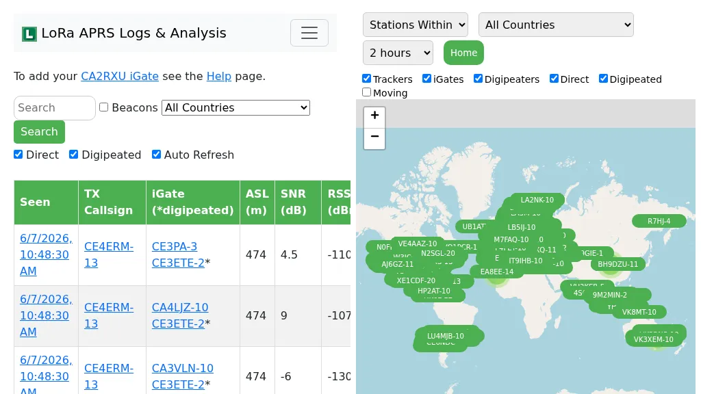 Demonstrates the operational status and reach of the LoRa APRS infrastructure, providing a live mapping and logging service for network participants. Users can verify network coverage, monitor _iGates_, and track mobile stations, observing messages and real-time network activity. The platform offers insights into station locations and data flow within the LoRa APRS system, which is crucial for understanding the performance of LoRa technology in Automatic Packet Reporting System applications. This utility helps amateur radio operators understand where transmissions are being received and processed by iGates, and how mobile units are moving within the network. The site's analysis tools provide RF performance monitoring and metrics, enabling users to assess network efficiency and identify areas for improvement. For example, operators can see how many packets are received by specific iGates, or track the path of a mobile station over a **100 km** range, offering practical insights into signal propagation and network reliability for _packet radio_ enthusiasts.
 -
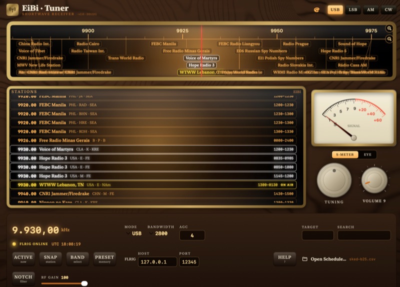 EiBi-Tuner-v2 is an open-source macOS application designed to control amateur radio transceivers via the FLRIG interface, leveraging the EiBi-list for frequency management. This software provides a graphical user interface that emulates an older radio, allowing operators to tune their rigs based on the extensive EiBi database of broadcast stations and utility frequencies. The application is specifically compiled for macOS, offering a native experience for users of Apple's desktop operating system. The software's primary function is to simplify frequency selection and rig control by integrating the EiBi-list, which contains thousands of known frequencies, with FLRIG's robust transceiver control capabilities. This integration allows for rapid QSY to documented frequencies, potentially enhancing DXing and SWL activities by providing quick access to a vast array of signals. The open-source nature permits community contributions and modifications, ensuring adaptability and ongoing development for specific amateur radio operational needs.