Search results
Query: build
Links: 859 | Categories: 99
Categories
- Antennas > 160M
- Antennas > 20M > 20 meter Dipole Antennas
- Antennas > 20M > 20 meter Yagi antennas
- Antennas > 40M > 40 meter Magnetic Loop Antennas
- Antennas > 6M > 6 meter Moxon Antennas
- Antennas > 6M
- Manufacturers > Antenna Parts > Aluminium Tubing
- Technical Reference > Amplifiers
- Manufacturers > Antenna Parts
- Shopping and Services > Antenna Parts
- Technical Reference > Antenna Rotator
- Technical Reference > Antenna Switch
- Technical Reference > APRS
- Technical Reference > Attenuators
- Technical Reference > ATV
- Antennas > Baluns
- Technical Reference > Beacon keyers
- Antennas > Capacitive
- Antennas > Feed Lines > Choke
- Antennas > CobWebb
- Technical Reference > Receivers > Crystal radio
- Operating Modes > Satellites > CubeSats
- Antennas > Delta loop
- Software > Developer Resources
- Technical Reference > Digital ATV projects
- Antennas > EH
- Manufacturers > Electronic Components
- Antennas > End-Fed
- Antennas > Fan Dipole
- Manufacturers > Antenna Parts > Fiberglass tubing
-
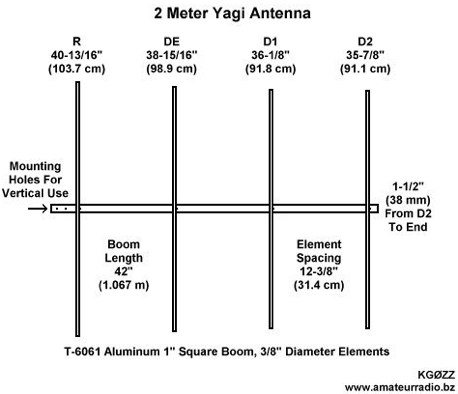 An interesting article on building a 4 elements yagi antenna with gamma match for the 2 meter band. This article include two videos demonstrating assembling procedure by KG0ZZ
 -
 Demonstrates the construction of two distinct wideband RF preamplifiers, detailing their component requirements and performance characteristics. The first design leverages monolithic microwave integrated circuits (MMICs) such as the MAR-6, MAR-8, or PGA103, offering a broad frequency response from DC to 2 GHz with a gain of 22.5 dB at 100 MHz and a noise figure typically below 3 dB. This MMIC-based amplifier incorporates protection against power supply transients and features a 50 Ohm input/output impedance, operating from an 8-20 volt supply with low current drain. The second preamplifier design utilizes a BSX-20 transistor, providing amplification across the 14 MHz to 550 MHz range. This simpler, more economical build achieves an average gain of 12 dB at 145 MHz and a noise figure of approximately 1.1 dB. It operates from a 7-15 volt battery supply with a current draw of 6 mA. Both projects emphasize critical construction techniques, such as maintaining short RF connections, ensuring 50 Ohm impedance paths, and mounting the circuit within a shielded enclosure to optimize performance and minimize noise. The resource also discusses phantom power options for antenna-mounted preamplifiers and precautions for use with transceivers, including output protection diodes and static bleeders.
 -
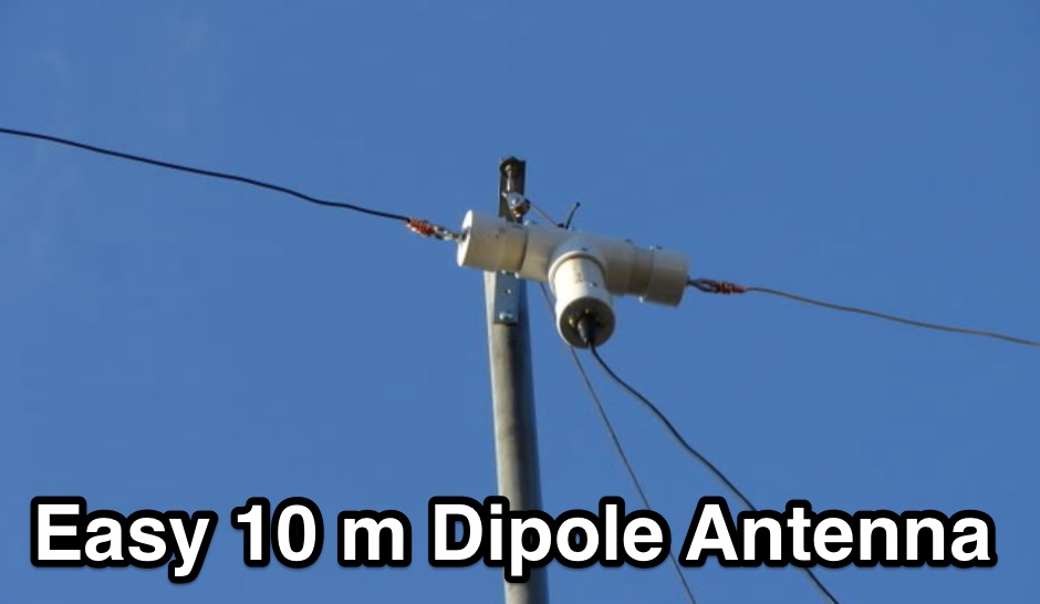
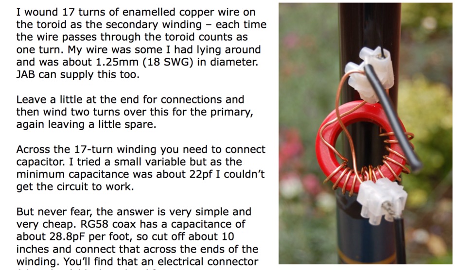 A monoband end-fed half wave for 10m, 20m or any other HF band, includes a PDF with detailed information to build your own monoband or multiband antenna
 -
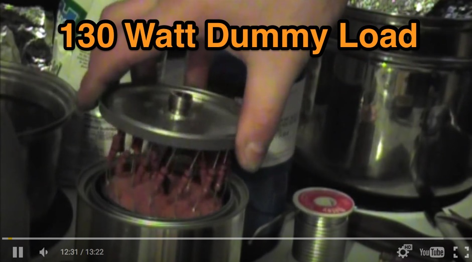 Video, how to build a 130 Watt Dummy Load for HF amateur radio
 -
 Amateur Radio and Commercial Radio licencing exam practice. You can visit the Technician, General or Extra license pages where you can pick and choose the topics to practice so you can build up to a complete exam.
 -
 How to easy connect two Pc together with a Ethernet Lan
 -
 Designing **Moxon Rectangle** antennas often involves an urge among builders to find simple "magic formulas" for element lengths. L. B. Cebik, W4RNL, argues against this simplistic approach, emphasizing that antenna dimensions do not scale linearly and are influenced by factors like wire size and height above ground. This resource presents a procedure for developing sensible design equations, starting with uniform-diameter elements and perfectly conductive materials, with adjustments for real-world materials like copper and aluminum. The core of the method involves judicious **NEC modeling** (versions 2, 3, or 4) to create a baseline dataset for regression analysis, ensuring models meet specific performance standards for gain, front-to-back ratio, and feedpoint impedance. The derived equations, presented as a BASIC program, allow for calculating Moxon dimensions (A through E) based on wire diameter in wavelengths and design frequency. W4RNL demonstrates the efficacy of these equations by designing and testing Moxon Rectangles for 7.15 MHz (AWG #12 wire), 28.5 MHz (1" tubing), and 146 MHz (0.125" rod). Modeled performance data, including gain, front-to-back ratio, and feedpoint impedance, are provided for both perfect and real-world materials, showing high efficiency and close adherence to design goals. The article also references a standalone Windows program by AC6LA that automates these calculations and generates EZNEC or NEC models.
 -
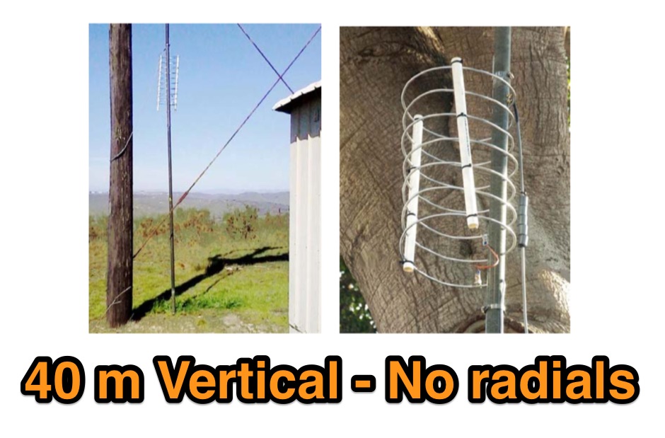 40 meter vertical antenna construction, a shortened easy-to-build vertical, with no-radials, made from surplus military camouflage poles
 -

-
 Yet another G5RV antenna plan to build a G5RV Antenna for 80 to 10 meters usage
 -
 A _Topfkreis_ antenna, also known as a "bicycle pump" antenna, is presented as a simple vertical design for the 70 cm band. This variant of the J-pole antenna is notable for not requiring a ground plane, simplifying deployment. The construction details specify using aluminum tubing for the radiating element, with precise measurements for the quarter-wavelength outer tube (32 mm diameter) and the three-quarter wavelength inner sliding tubes (10 mm and 8 mm). Feeding is via a 50-ohm coaxial cable connected 90 mm from the base of the central tube. This design can achieve a gain of **4 to 6 dB** when properly tuned using the adjustable radiating element. The article details the fabrication of a critical aluminum washer, suggesting a method using a hole saw and a drill press as a lathe for precise adjustment. The illustrated example is specifically for the 70-centimeter band, and the author, Pop, clarifies construction points in the comments, including material choices and assembly techniques, ensuring a robust build for VHF/UHF operation.
 -
 This project will enable you to build a monoband long wire inverted vee with 3/4 wave length sides that will have a bit of gain
 -
 N4ATS - Devoted to the Yaesu FL-7000 Amplifier. I have been rebuilding, repairing, and applying modifications to the Yaesu FL-7000 amplifier for 15 years. Over 200 units completed and counting!
 -
 Cheap and EZ to build Bi-Directional VHF & HF antennas with gain
 -
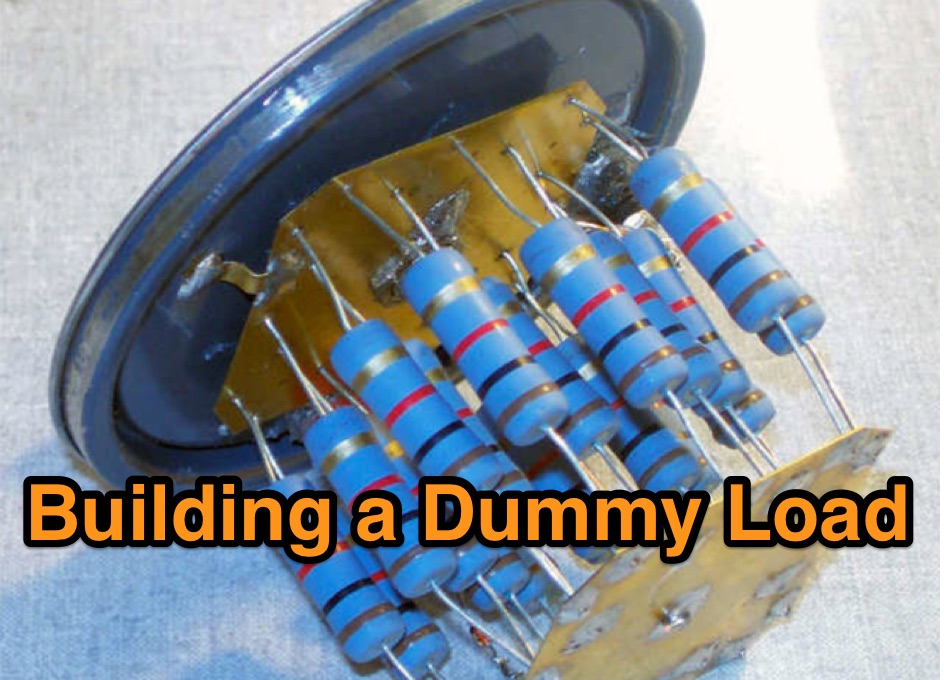 Building a Dummy Load and Measuring Power Accurately
 -
 How to make your ham radio system mobilemany ham radio operators carry radios for fun, safety and public service activities. radios for both vhf and hf frequencies can easily be installed in vehicles.
 -
 Presents a detailed construction guide for a **Quadrifilar Helix Antenna** (QHA) optimized for 137 MHz, specifically for receiving weather satellite transmissions. The resource outlines the author's experience building previous QHA designs, highlighting challenges with tuning and nulls, and then focuses on a refined design by John Boyer, documented by Steve Blackmore, which proved easier to build and yielded superior reception. The guide provides precise element dimensions, including 1.5m of 32mm PVC pipe for the mast and 8mm soft copper tubing for the helix elements. It specifies lengths for horizontal tubes (190mm, 90mm) and helix elements (903mm, 1002mm), along with instructions for drilling, assembly, and forming a **balun** by wrapping RG58 coax around the mast. The text emphasizes critical steps like ensuring elements are square and twisting in the correct direction to avoid phase issues. It includes references to original QST articles by Buck Ruperto (W3KH) and the WxSat program for decoding satellite transmissions, contextualizing the antenna's purpose. The article concludes with a sample NOAA 12 image from September 1998, demonstrating the antenna's reception capabilities.
 -

-
 This project is an attempt to build a portable standalone VNA (Vector Network Analyzer).
 -
 This resource details the conversion of an 80m elevated vertical antenna to include 160m operation, focusing on a relay-switched design over a trap-based approach. It presents specific feedpoint impedance values, such as **32 ohms** for 80m and **14 ohms** for 160m, and discusses the challenges of SWR drift encountered with the prior trap system during RTTY contesting. The article thoroughly explains the design choices for elevated radials, referencing _N6LF QEX data_ to debunk common myths regarding radial length and height, demonstrating that non-resonant radials can offer superior current uniformity. The construction section provides practical insights into building the vertical, including guying strategies, material selection from scrap pipe, and weatherproofing the relay assembly. It highlights the use of a common mode choke for the relay switching line, measuring approximately 5K ohms on both 160m and 80m, and details the L/C matching network's role in achieving a 50-ohm match at the end of a 300-foot RG-11 run. The author describes a precise VNA-based radial trimming procedure, achieving resonant values within a 3 KHz range. The content emphasizes the practical application of theoretical antenna principles, particularly concerning the interaction between the vertical element, cap hats, and the matching network. It offers a candid assessment of component selection, such as using junkbox parts and acknowledging the need for future upgrades to static drain resistors. The article serves as a comprehensive case study for advanced antenna builders tackling multi-band vertical designs.
 -
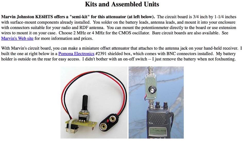 Build An Offset Attenuator by Joe Moell K0OV as featured in Homing In for May 1998
 -
 Simple, easy to build, low cost, compact, multiband By Robert Wilson, AL7KK
 -
 Pictures, photos, source code and plans to build a logging frequency counter
 -
 An interesting Elecraft KX3 go box, for a total of 1,6 Kg 3,5 lbs with list of needed parts to build your own box by OE2ATN
 -

-
 A Moxon rectangle antenna design for the 11-meter band is presented, offering a compact and lightweight solution for directional HF DX operation. This two-element parasitic array, popular among amateur radio enthusiasts, provides considerable directional gain and lower noise on horizontal polarization. The design is suitable for both 27 MHz Citizens Band (CB) and the lower portion of the 28 MHz amateur radio band, making it versatile for operators interested in either service. Construction can utilize materials like bamboo, squid poles with wire elements, or aluminum tubing on a central boom. The article includes a plan view diagram with specific dimensions (A-E) in centimeters and inches for building the antenna, such as a 392.09 cm (154 3/8 inch) driven element. The Moxon configuration inherently presents a 50 Ohm load to the transceiver, often eliminating the need for an external matching unit or balun. Performance data for an antenna mounted at approximately 30 feet indicates a gain of 10-11 dBi and a frequency range of 27.300 MHz to 28.300 MHz. The design is noted for its excellent front-to-back rejection, with tested signal drop-offs from S5-S7 to S2 when turned, demonstrating effective suppression of unwanted signals.
 -
 Constructing a portable, high-gain antenna for _AO-40_ satellite operations presents unique challenges, particularly regarding mechanical stability and parabolic accuracy. This resource details the build of a 1.2-meter "brolly dish" antenna, utilizing a non-conducting fiberglass umbrella frame as its foundation. The project outlines a method for achieving a parabolic shape using stressed aluminum fly screen mesh, guided by practical geometry and a temporary dowel template. Key steps include selecting an appropriate umbrella with a suitable f/D ratio (ideally >0.25), removing the original fabric, and precisely cutting and attaching eight segments of fly screen to the struts to form the reflective surface. The construction process, which took approximately five hours for the author, _G6LVB_, resulted in a dish with an f/D of 0.27 (depth=270mm, diameter=1160mm, f=310mm). The article also describes a modification to a _TransSystem AIDC_ feed, incorporating a PCB reflector behind the dipole for easier mounting. Performance tests at a squint angle of 15 deg and a range of 50,000km yielded a signal-to-noise ratio of 33dB on the S2 beacon and 23dB for SSB signals, indicating strong reception. The author notes that the modified umbrella may not close fully without risking surface disfigurement.
 -
 W6/PA0ZN CATV tuner based Spectrum Analyzer Building Project
 -
 If you want to build a repeater, this is the right place to start. Includes construction projects and reviews of repeater hardware available in the market.
 -
 The page is about the 144 Mhz Dirty Beacon project, a VHF beacon keyer by 9A4QV. It provides technical information, project details, and resources for amateur radio operators interested in beacon keyers. The content is useful for those looking to build or learn about VHF beacon keyers.
 -
 A 20-meter vertical _Moxon_ antenna, designed for portable operation, is detailed with specific dimensions for its driven and reflector elements. The project outlines the construction process, including the use of PVC pipe for the frame and #14 AWG insulated wire for the elements. The antenna's compact size and directional characteristics make it suitable for field day operations or limited space environments, offering a gain of approximately 5.5 dBi and a front-to-back ratio of 20 dB. Testing revealed a 1.2:1 SWR at 14.250 MHz, demonstrating good impedance matching across the target frequency range. The _Moxon rectangle_ design provides a clean radiation pattern with minimal side lobes, which is advantageous for reducing QRM from unwanted directions. This build offers a practical solution for hams seeking a lightweight, easily deployable directional antenna for 20 meters without the complexity of a full-sized Yagi.
 -
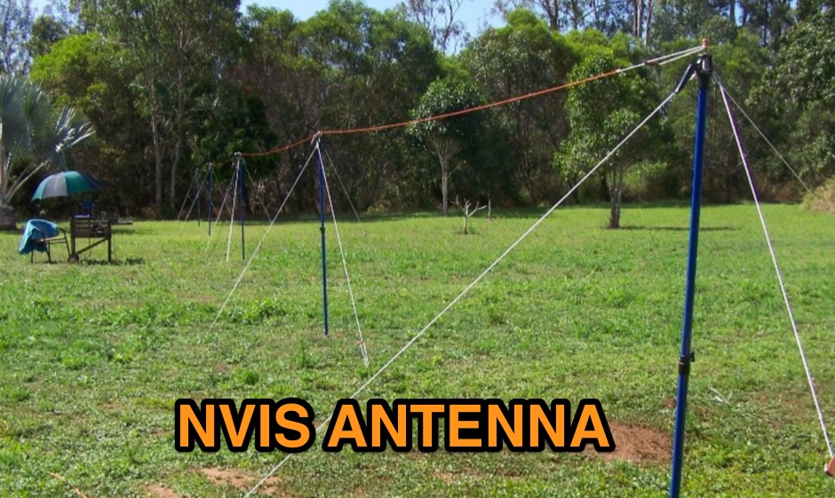 How to homebrew a ENVIS antenna for 80 and 40 meters band
 -
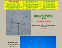 Construction Details for 50MHz-Yagis in DK7ZB-Design
 -
 The ZS6BKW antenna, a popular multiband wire antenna, offers improved band matching compared to the traditional G5RV. This construction guide details the process, beginning with specific dimensions: 13.11 meters (43 feet) for the 450-ohm ladder line and initial dipole arm lengths of approximately 14.8 meters each. It emphasizes the critical role of an _antenna analyzer_ for accurate tuning, particularly for determining the velocity factor of the ladder line and achieving a 1:1 impedance match. The article outlines the materials required, including a 1:1 current balun, 450-ohm window line, wire for the dipole arms, and a 50-ohm non-inductive resistor for testing. It provides a step-by-step procedure for cutting the ladder line to its electrical half-wavelength, explaining how to calculate the velocity factor using measured and free-space frequencies. For instance, a measured 50-ohm impedance at 12.54 MHz with a calculated free-space half-wavelength frequency of 11.44 MHz yields a velocity factor of 0.91. Final adjustments involve hoisting the antenna to its operational height and fine-tuning the dipole arm lengths to achieve optimal SWR, specifically targeting 14.200 MHz. The _ZS6BKW_ design is noted for its performance on 80m, 40m, 20m, 10m, and 6m, though it is not optimized for 15m operation. The author, _VK4MDX_, shares practical tips for durable construction using stainless steel wire and cable clamps.
 -
 Presents the design and performance of a 4-element wire Yagi antenna for the 40-meter band, building upon VE3VN's earlier 3-element switchable wire Yagi. The resource details the antenna's evolution, highlighting the transition from a 3-element to a 4-element configuration and the resulting improvements in gain and front-to-back ratio. It provides specific insights into the antenna's construction and expected operational characteristics. VE3VN shares insights from field results, noting the antenna's performance on 40 meters. The discussion includes the antenna's pattern and matching characteristics, crucial for any DXer or contester looking to optimize their signal on this popular HF band. The author's experience with the previous 3-element design informs the enhancements made to this 4-element iteration. The article includes a visual representation of the antenna's current view, offering a practical perspective on its physical layout. It serves as a valuable reference for hams considering a directional wire antenna for 7 MHz operations, demonstrating a practical approach to achieving enhanced directivity and gain.
 -
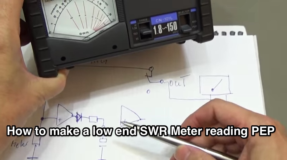 Building a PEP Power circuit for all analogue watt-meter
 -
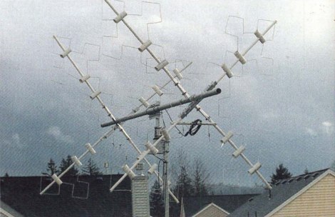 Presents the construction of a 10-meter Fractal Quad Yagi (FQY) antenna, detailing the design principles and practical build steps. The article highlights the antenna's compact size, with elements measuring just over 4 feet per side, making it suitable for easy erection and rotation with a TV rotator. It claims an impedance close to 50 ohms, allowing direct feed with 50-ohm coax, and specifies a 3 dBd gain with a front-to-back ratio exceeding 25 dB. Bandwidth is reported at 500 kHz for less than 2:1 VSWR. The resource includes a segment chart (Fig. 1) illustrating the precise lengths for each wire segment of the driven element and reflector, noting adjustments for different wire diameters. Construction utilizes readily available materials such as #9 aluminum ground wire and plastic water pipe for spreaders. The author, _KF7BS_, describes fabricating the framework, bending the fractal elements, and mounting them, including modifications like adding a small stub for reflector tuning. A materials list is provided, detailing items like 40-ft rolls of #9 Radio Shack aluminum ground wire and 1/2-inch plastic water pipe. Scaling equations for the driven element are discussed for different frequencies, such as designing for the CW band. The article references _Chip Cohen NIIRV_'s_ original _Fractenna_ website as the inspiration for the design.
 -
 The W4NFR 40-meter mobile vertical antenna project details the construction of a mobile antenna system, drawing inspiration from a July 2011 QST article by VE6AB. The design simplifies the top hat by integrating an 8-spoke top hat from Tar Heel Antenna. The resource outlines the tuning process, which involves adjusting the L1 coil for the desired band segment and then fine-tuning SWR with an L2 coil at the feed point. The author achieved a 1:1 SWR at 7.150 MHz with this configuration. The project includes specific instructions for adding anti-sway supports to ensure stable operation and reduce physical stress on the ball mount during vehicle motion. Visual aids such as drawings of the 40-meter mobile antenna, detailed views of the coil and top hat assembly, and an illustration of the ball and spring mount are provided to guide the builder through the construction and installation phases. The content focuses on practical implementation and tuning for optimal performance on the 40-meter band.
 -
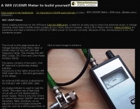
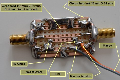 An home made SWR meter for 2.4 GHz. A DIY SWR meter that allow precise measurements and calibration of any WiFi antenna. This is test equipment everyone who build wifi antennas should have in their shack. Article is in french and include some videos.
 -
 Huge amount of relevant information you should know before building a tower
 -
-
 Technical and modification information on Astron Power Supplies compiled from a number of different sources by Mike Morris WA6ILQ
 -
 A 2m Moxon antenna project, designed for the 145 MHz amateur radio band, provides a compact, directional solution for VHF communications. This resource details the construction process, specifying materials like PVC pipe for the frame, copper wire for elements, and a SO-239 connector for the feedpoint. The design emphasizes ease of build for hams seeking a gain antenna with good front-to-back ratio for local ragchewing or contesting. The project outlines precise element lengths and spacing, crucial for achieving the desired impedance and radiation pattern. It includes a visual representation of the antenna's dimensions and assembly, allowing for straightforward replication. The Moxon's inherent characteristics offer a practical alternative to larger Yagi arrays, particularly for portable operations or restricted spaces, while still delivering effective directivity and gain.
 -
-
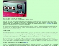 Robert Norgards KL7FM's, notes on upgrading the Heathkit SB-200
 -
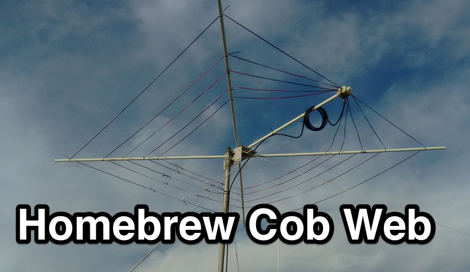 Homebrew a cobwebb antenna for the HF bands. This page describe a cobwebb multiband antenna resonating on 14 18 21 24 and 28 MHz. The cobweb antenna model can be considered a fan dipole, or better, multiple dipoles fed in parallel.
 -
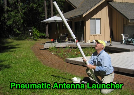 How to build the Quickie Pneumatic Antenna Launcher
 -
 Calculate EH Antenna, 20m 40 80m. Fotos, Original eh antenna building.
 -
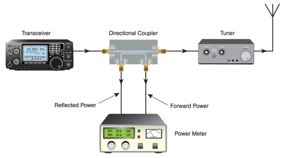 Every ham needs an RF power meter. Here is a high performance unit to build at home.
 -