Search results
Query: Radio Band
Links: 892 | Categories: 54
Categories
- Ham Radio > Band Plans
- Operating Modes > NPR New Packet Radio
- Operating Aids > Radio Spectrum
- DX Resources > Beacons > 10 meter beacons
- Antennas > 23cm
- Antennas > 2M
- Antennas > 30M
- Antennas > 4M
- Antennas > 6M > 6 meter J-Pole Antenna
- Antennas > 60M
- Operating Modes > 70 MHz
- Operating Modes > Aircraft scatter
- Radio Equipment > VHF-UHF Handhelds > Baofeng UV-3R
- Technical Reference > Beacon keyers
- DX Resources > Beacons
- Technical Reference > Radio Frequency Interference > BPL
- DX Resources > Clusters
- Antennas > CobWebb
- Radio Equipment > Contest Hardware
- Antennas > End-Fed
- Manufacturers > Filters
- Antennas > G5RV
- Antennas > Halo
- Antennas > HB9CV
- Antennas > HexBeam
- Technical Reference > Amplifiers > HF Amplifiers
- Operating Modes > HF Operations
- Radio Equipment > HF Vertical Antenna
- Manufacturers > Antennas > VHF UHF Microwave > HT Antennas
- Radio Equipment > VHF-UHF Mobile > ICOM IC-2720H
-
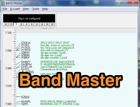 Band Master is a program for Radio Amateurs that downloads DX spots and displays them in different ways, including a graphical band map. It can be used either as a stand alone application or as part of a logging or contesting software. Price USD 25
 -
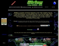 Presents _DirLog_, a freeware logging application specifically developed for the 11-meter CB band, catering exclusively to members of the _Alfa Tango Group_. The software facilitates the recording and management of contacts, providing a dedicated tool for CB operators to maintain their station logs. Its development spans from 1997 to 2025, indicating a long-term commitment to its maintenance and evolution by its author, 1AT069 Enio. This specialized logbook offers features tailored for CB operations, allowing users to track their contacts within the 27 MHz band. While primarily focused on CB logging, its structure and functionality could be compared to amateur radio logging software in terms of data entry and retrieval. The exclusivity to Alfa Tango members suggests a community-specific utility, fostering organized record-keeping among its users.
 -
 CB2HAM is a group for licensed radio amateurs focussed on converting quality CB radios over to the Ham bands.
 -
 Antenna Warehouse provides a range of certified quality wire products for amateur radio and general communication applications. Their inventory includes Francis antennas, known for their robust construction, alongside the versatile Select-A-Tenna series. The company also stocks Solarcon 10/11 meter base antennas, catering to specific band requirements for 27-28 MHz operations, and various Wilson antenna models. Beyond product sales, Antenna Warehouse offers services such as antenna tower installation, repair, and removal. These services support the complete lifecycle of antenna systems, from initial setup to maintenance and decommissioning. The product selection emphasizes components for both fixed station and mobile installations.
 -
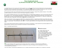 A suitable high gain 70cms antenna for SOTA operation was sought that did not have the drawbacks of a long Yagi antenna, principally a narrow beamwidth and bandwidth.
 -
 Illustrates the global distribution of **DX-Cluster** nodes through an interactive map interface, enabling radio amateurs to visualize and access real-time DX spots. The resource provides direct TELNET and HYPER links for each node, facilitating immediate connection to various clusters for up-to-the-minute propagation information and station activity. This visual approach simplifies the process of locating and connecting to a suitable DX-Cluster, whether for local or international DXing. Amateurs can use this tool to quickly identify active clusters in different geographic regions, which is particularly useful for **DXpedition** planning or contest operations. The direct links streamline access, bypassing manual configuration for many cluster types. It serves as a practical aid for operators seeking to monitor band conditions, find rare DX, or participate in competitive operating events by leveraging aggregated spotting data.
 -
-
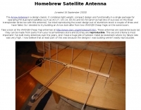 The Arrow Antenna is a design classic: it combines light weight, compact design and functionality in a single package for operating FM dual band satellites such as AO-27, UO-14, SO-41 and SO-50
 -
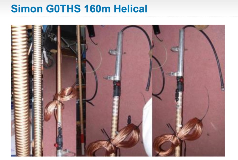
 The 6 Band Inverted L Antenna MK3 is a versatile multiband antenna designed for amateur radio operators. This antenna covers 160m, 80m, 40m, 20m, 15m, and 10m bands, making it suitable for a wide range of HF communications. The design is based on a W3DZZ configuration, incorporating traps for optimal performance. The MK3 version features a sturdy 5/8th CB mast, replacing the original timber mast, which enhances durability against harsh weather conditions. The antenna's construction allows for effective operation, particularly on the 40m band, where it has been successfully used to contact distant locations including ZL, VK, and Antarctica. Constructing this antenna requires careful attention to detail, especially regarding the radials and grounding. The traps resonate at specific frequencies, and additional resources are available for building coaxial traps. The antenna is designed to work efficiently without an ATU on the lower bands, while higher bands may require tuning. This project is ideal for both beginner and intermediate operators looking to enhance their station with a reliable multiband antenna.
 -
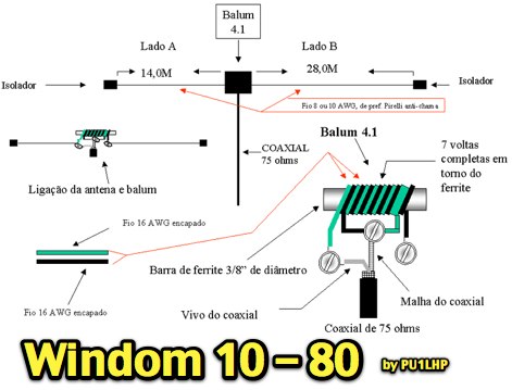 Project of a windom multiband antenna for 10 to 80 meters in portuguese
 -
 Modifying the _ICOM IC-706MKII_ transceiver for out-of-band transmit capability involves specific surface-mount device (SMD) removal on the main circuit board. This procedure enables transmit functionality from 0.5 MHz to 200 MHz, excluding the commercial FM-Wide broadcast band, significantly expanding the radio's operational frequency range. The modification requires careful handling of small components and a fine-tipped, low-wattage soldering iron. Prior to beginning, all programmed memories and initial setup configurations must be noted, as the modification process will erase them. The instructions detail the necessary tools, preparation steps, and the precise location of the two SMD diodes to be removed. These diodes are situated near an oblong crystal can and a test point labeled _CP3_ on the main board. Successful completion returns the unit to its default configuration, necessitating manual reprogramming of memory channels and initial settings. This project is suitable for operators with experience in SMD work and fine soldering.
 -
 Described is a simple inverted-V antenna which, when used with a balanced ATU, can be used on all the main Radio Amateur HF bands (80, 40, 20, 15 and 10m). The cental support is made in such a way that the wire can be coiled up for storage when the antenna is taken down.
 -
 Theory, Modeling, and Practical Applications By W5JCK, presentation in PDF File. This presentation focuses on Near-Vertical Incidence Skywave (NVIS) antennas, which are crucial for short-range radio communications, particularly in military and emergency contexts. It explores NVIS theory, antenna models, and installation criteria while debunking common myths about reflectors. Key topics include usable frequency bands, optimal installation heights, and the impact of soil quality on performance. The presentation outlines the best bands for daytime and nighttime use, emphasizing the importance of understanding propagation characteristics to enhance communication effectiveness within 200 to 300 miles.
 -
 Comparison chart between Cushcraft R8, Hy-Gain AV640 , Butternut HF6V, Gap Titan and Eco 7+
 -
 The article "Exploring the World of 10 Meter Beacons" by Ken Reitz, KS4ZR, provides an in-depth look at 10-meter beacon operations, focusing on their utility for propagation analysis. It details FCC Rules part 97.203 governing beacon stations, including license requirements, power limits (under 100 watts), and the specified band segment of 28.200-28.300 MHz for U.S. operations. The content highlights the diversity in beacon construction, from converted CB radios to home-brew QRP transmitters, and discusses the robust operating conditions these 24/7 stations endure. The resource presents several case studies of active 10-meter beacon operators like Ron Anderson KA0PSE/B, Domenic Bianco KC9GNK/B, and Bill Hays WJ5O/B, detailing their equipment, antenna setups, and typical signal report volumes. It also introduces the NCDXF/IARU International Beacon Project, which features 18 synchronized beacons worldwide transmitting on 28.200 MHz at varying power levels (100W, 10W, 1W, 100mW) to facilitate propagation testing. The article also covers the PropNet Project utilizing PSK31 on 28.131 MHz and the 250 Synchronized Propagation Beacon Project on 28.250 MHz. Practical advice for monitoring includes using the RST reporting method, understanding the impact of the solar cycle on 10-meter propagation, and tips for setting up a personal beacon, such as frequency selection and power output considerations. The IY4M Guglielmo Marconi Memorial Beacon Robot on 28.195 MHz is also mentioned for its automatic QSO mode. The article concludes with a list of other resources for 10-meter beacon information.
 -
 IZ7GJX Comparing Kenwood TS-2000 to Icom IC-7000 on various ham radio bands
 -
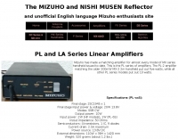 Mizuho Tsushin Co. was a small Japanese manufacturer of QRP radios and kits, shortwave receiver accessories, and AM broadcast band receiver kits and antennas
 -
 A 7 elements yagi beam monoband antenna for 14 Mhz by VE3GK
 -
 Online UK CB Radio shop specialising in UK CB Radio and 10m Amateur radio equipment. Scanners and multiband receivers also available.
 -
 A quarter-wave vertical antenna design for HF operation offers a practical solution for radio amateurs seeking a compact and efficient multi-band radiator. This project details the construction of a 5-band HF vertical, drawing inspiration from established commercial products such as the _DX COMMANDER_ and the MV6. The design emphasizes ease of assembly and disassembly, making it suitable for portable operations or installations with limited space. The article provides insights into various construction methods and offers practical tips for building a robust yet lightweight antenna. It highlights the benefits of a vertical configuration for DX contacts, particularly on the lower HF bands, and discusses real-world performance observations. The antenna is designed to cover multiple HF bands, providing versatility for various operating scenarios. Operators can achieve significant DX results with this type of antenna, often comparable to more complex arrays, especially when deployed with an effective ground system. The project aims to empower hams to build a capable antenna without significant financial outlay.
 -
 Homebrew a 2 meter 1/4 wave vertical antenna for the 146 mHz ham radio band
 -
 Constructing a Lindenblad antenna for 137MHz NOAA satellite reception involves specific design considerations for optimal performance. The resource details the use of 4mm galvanised steel fencing wire, 300-ohm television ribbon cable, and wood/plastic components for the antenna structure. Key dimensions for a 137.58MHz-resonant antenna are provided, derived from the ARRL Satellite Handbook, specifying s, l, w, and d as 42, 926, 893, and 654mm respectively. The antenna is designed for Right Hand Circularly Polarised (RHCP) signals, requiring the four folded dipole elements to be tilted clockwise by 30 degrees. A significant aspect covered is impedance matching between the antenna's 75-ohm impedance and a typical 50-ohm receiver input. A twelfth-wave matching transformer, constructed from 117mm sections of 50-ohm RG-58 and 75-ohm RG-59 coax with a 0.66 velocity factor, is described. The article also addresses coaxial cable and connector selection, recommending 75-ohm Type-N connectors for RG-6 cable in professional setups and F56/F59 connectors for general use, while strongly advising against PL-259/SO-259 connectors for VHF. Strategies for mitigating Radio Frequency Interference (RFI) are discussed, including antenna placement to shield from local TV transmitters and the use of commercial or DIY band-pass filters, such as cavity resonators or helical notch filters, along with ferrite chokes on coaxial cables. Antenna orientation is explored, noting the Lindenblad's 'cone of silence' directly overhead and its maximized sensitivity towards the horizon. An experimental vertical tilt of 90 degrees is presented as a method to improve overhead reception and reduce interference from strong horizontal signals, particularly relevant in high RFI environments like the Siding Spring Observatory site.
 -
 A project for a portable antenna for amateur radio satellite reception, for 2 meters and 70 centimeters bands
 -
 The RigPix database entry provides a comprehensive technical overview of the Icom IC-746 amateur HF/VHF transceiver, detailing its operational parameters and physical characteristics. It specifies the transmit frequency ranges across 10-160 meters plus WARC bands, 50-54 MHz, and 144-146/148 MHz, alongside receive coverage from 0.03-60 MHz and 108-174 MHz. The resource outlines supported modes including AM, FM, SSB, CW, and RTTY, noting a tuning step resolution down to 1 Hz and a frequency stability of ±5 ppm. Key electrical specifications are presented, such as a 13.8 VDC power supply requirement, current drain figures for RX (1.8-2 A) and TX (Max 20 A), and RF output power ranging from 5-40 W for AM and 5-100 W for FM, SSB (PEP), and CW. The entry details the triple conversion superheterodyne receiver system, listing IF frequencies at 69.01 MHz, 9.01 MHz, and 455 KHz, along with sensitivity ratings for various modes and bands. Transmitter section specifics include modulation systems and spurious emission levels. Additional features like a built-in auto ATU, electronic keyer, simple spectrum scope, DSP, and CI-V computer control are noted. The page also lists related documents, modifications, and an extensive array of optional accessories, including various filters, microphones, and external tuners, providing a complete profile of the IC-746.
 -
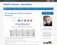
 Excel sheet containing technical comparisons of commercial HF portable antennas compiled by ON4SKY. Includes pictures, manufacturer, db gain, band coverage, F/B ratio, price, weight and dimensions.
 -
 An antenna system is more easily interfaced to a radio when the input reactance at the feedline terminals is low or close to series resonance
 -
 Details the offerings of Ham Buerger Inc., a company founded in 1965 to support the amateur radio community with communications products. The business provides a range of equipment, including Uniden Digital scanners, and maintains a section for equipment blow-out sales that feature professional 2-way radios and cell phones. Additionally, the company stocks hard-to-find NuTone products and provides repair services for most NuTone equipment. The site also references an Amateur Radio Band Plan and links to other ham radio resources, alongside a new product offering for RV and marine toilets, indicating a diversification beyond core amateur radio supplies.
 -
 JJ0DRC's HF multi-band delta loop antenna project, initially conceived during the waning peak of Cycle 23, addresses the common challenge of achieving effective DX operation from a small residential lot in Japan. Dissatisfied with a ground plane antenna's performance in SSB pile-ups, the author sought a beam-like solution without a tower, drawing inspiration from a JJ1VKL article in CQ Ham Radio Sep. 2000. The antenna, constructed in October 2000, employs two 7.2-meter fishing rods (37% carbon fiber, reinforced with cyano-acrylate glue and aluminum tape) and 1mm enameled wire, fed by an Icom AH-4 external antenna tuner. While the exact beam pattern remains unmeasured, JJ0DRC observed a significantly higher callback rate compared to dipole antennas, particularly on higher bands. The system's circumference length of 15-20m is crucial for maintaining a good beam pattern across HF bands, though performance on lower bands like 80m, 40m, and 30m becomes less directional as the length deviates from a full wavelength. Ongoing maintenance addressed degradation issues, including aluminum tape cracking and wire breakage at connection points due to strong winds (often exceeding 10-15m/s in winter). The author reinforced rod connections with IRECTOR PIPE SYSTEM components and INSU-ROCK ties, and improved wire attachment methods using Cremona rope and epoxy bond to enhance durability.
 -
 Presents the design and construction of the OK2FJ Bigatas, a portable, automatically tuned vertical antenna covering 80 through 10 meters. It details two distinct control systems: one utilizing BCD band data from Yaesu FT-857/897 transceivers, and another employing voltage level sensing for the Yaesu FT-817. The resource provides specific instructions for building the antenna's radiating element, loading coil with switchable taps, and the control circuitry, emphasizing the use of readily available components. The article outlines the physical construction of the antenna, including the use of duralumin tubes for the radiator and a PVC tube for the coil form. It specifies coil winding details, tap points, and the integration of radial wires for ground plane operation. The control electronics section provides schematics and component lists for both the BCD decoder (using a 74LS42 IC) and the voltage comparator (using an _LM3914_ bargraph driver), enabling rapid, automatic band switching without the minute-long tuning delays common in other systems. Crucially, the antenna achieves rapid band changes, with typical SWR values centered on common operating segments, such as **3.7 MHz** for 80m SSB. It also discusses modifications for CW operation on 80m and the trade-offs between antenna efficiency and full-range automatic tuning on higher HF bands, where manual adjustment of radiator length is suggested for optimal performance on 15m, 12m, and 10m. The resource includes construction photos and a discussion of cable requirements for reliable operation.
 -
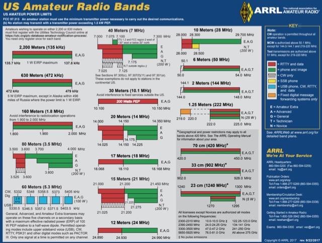 US Amateur Radio Band Plans by ARRL
 -
 Overview, summary, tutorial about the log periodic antenna or aerial used for wideband RF antenna applications
 -
 Amateur Television (ATV) operations, particularly within the Arizona region, require dedicated resources for technical information, operational guidance, and community engagement. This club provides a focal point for hams interested in transmitting and receiving video signals on amateur bands. Members engage in local ATV repeaters, participate in technical discussions, and share knowledge on video modulation schemes, antenna designs, and station configurations. The club supports activities ranging from local simplex contacts to wider area repeater usage, fostering skill development in this specialized mode. The organization maintains a roster of club officers and offers membership opportunities to local amateurs. It also curates offsite links to other ATV resources, expanding the knowledge base available to its members and the broader amateur community. The club's emphasis on ATV helps propagate interest and technical expertise in a mode that combines traditional RF engineering with video technology.
 -
 7.5 MHz wideband audio delivered via AMC-7 satellite transponder 5 provides a robust platform for disseminating amateur radio news. This service caters to operators seeking timely updates on regulations, technology, and DX news. The bulletin is accessible in both MP3 and RealAudio formats, ensuring compatibility with a wide range of devices and listening preferences. Regularly updated content keeps amateur radio enthusiasts informed about the latest developments in the hobby. The service covers a broad spectrum of topics, including contesting, digital modes, and antenna technology. By leveraging satellite and internet distribution, it reaches a global audience, making it a vital resource for operators worldwide. Listeners can expect a consistent flow of information, with new episodes released frequently. The service's commitment to providing high-quality content ensures that amateur radio operators remain well-informed and engaged with the community.
 -
 The Kenwood TH-F6A handheld transceiver can achieve an extended transmit frequency range of 137-174 MHz, 216-235 MHz, and 410-470 MHz by removing a specific diode and chip resistor from the main PCB. This modification also expands the receive range on the A-band to 142-152 MHz, 216-235 MHz, and 420-450 MHz. For the TH-F7E, the transmit range extends to 137-174 MHz and 410-470 MHz, with a corresponding receive range on the A-band. Performing these hardware changes will reset and initialize the radio's memory contents, necessitating prior backup of important channel frequencies. Instructions are provided for constructing a homemade PC programming cable compatible with the Kenwood TH-G71A, TH-F6A, and TH-F7E. The interface utilizes an RS-232-to-logic (0-3.3V) level-shifter and a full-duplex serial connection, adapting the Kenwood PG-4S cable schematic for the TH-G71's 2.5mm and 3.5mm phono plugs. Specific schematic tweaks include changing R1 from 150 ohms to 1K ohm to optimize power from the serial port and adding a 150K ohm resistor between the Radio TXD and ground to manage the 3.3V I/O pin. Detailed plug pinouts for the 2.5mm and 3.5mm connectors are presented, with the interface's TXD connecting to the ring of the 2.5mm plug and RxD to the shield of the 3.5mm plug. Ground connects to the shield of the 2.5mm plug, while the tips of both plugs are no-connects. Debugging procedures cover verifying positive and negative power rails from the serial port, checking component polarities, and testing level-shifting and inversion functions of the interface. Software setup involves enabling "TC ON" (Menu 15 for TH-G71, Menu 9 for TH-F6) and using Kenwood's MCP programming software.
 -
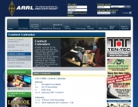 The **ARRL Contest Calendar** presents a detailed schedule of upcoming amateur radio competitions, encompassing both ARRL-sponsored events and significant non-ARRL contests. It provides essential operational details for each entry, such as specific operating periods, eligible bands, and permitted modes, enabling contesters to plan their participation effectively. The resource also links to official rules, soapbox reports, and QST results, offering a comprehensive overview of past and future contest activity. Users can navigate through monthly listings to identify contests of interest, with direct access to detailed information pages for each event. The calendar serves as a central hub for contest operators seeking to confirm dates, understand exchange requirements, and review post-contest analyses. Its utility extends to both seasoned contesters and those new to competitive operating, providing a structured approach to contest participation. The platform integrates various contest-related resources, including links to **Contest Corral** entries for non-ARRL events, ensuring a broad scope of coverage. This aggregation of information streamlines the process of finding contest schedules and associated documentation, making it a practical tool for the amateur radio contesting community.
 -
 Pictures of a 2 meter, 220, 440 copper J-Pole antennas
 -
 This project outlines the construction of a 3-element reversible quad antenna specifically designed for the 40-meter band. The materials required include pushup towers, pressure-treated posts, insulated wire, and various electrical components such as relays and a balun. The construction process is straightforward, beginning with the installation of the posts in a straight line, followed by the assembly of the antenna elements and their elevation to the desired height. The antenna's design allows for directional signal reception, making it ideal for operators looking to enhance their communication capabilities on the 40-meter band. The project includes detailed instructions on tuning the antenna for optimal performance, ensuring that operators can achieve the lowest SWR possible. Additionally, the design can be adapted for other bands by extrapolating dimensions, providing versatility for amateur radio enthusiasts. Overall, this reversible quad antenna project is suitable for both beginners and experienced operators, offering a practical solution for improving signal strength and directionality in 40-meter communications.
 -
 Band audio equalizer and noise gate compatiable with ICOM, KENWOOD, YAESU and other radios
 -
 A monoband yagi for 14 MHz a PDF article from 73 amateur radio magazine by AB4GX
 -

-
 CyberDX-CW is a software simulation of an amateur radio station monitoring the world. Generates a simulated radio environment, where the operator can tune all of the HF bands and actually hear computer generated station activity
 -
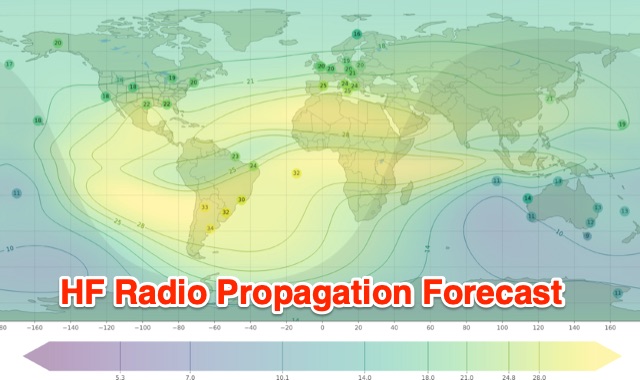 Understanding high-frequency (HF) skywave propagation is crucial for amateur radio operators seeking to optimize long-distance communications. This resource details the fundamental principles of HF radio propagation, including the properties of electromagnetic waves, the characteristics of various HF bands, and distinct propagation modes such as skywave, ground wave, and line-of-sight. It places significant emphasis on the ionosphere's pivotal role in refracting HF waves, explaining how solar activity directly influences ionospheric conditions and, consequently, propagation paths. The resource integrates real-time monitoring capabilities, featuring dynamic charts and data from DX clusters, WSPRnet, and the Reverse Beacon Network, which allow users to track current band activity and propagation conditions globally. It also delves into advanced topics like Near Vertical Incidence Skywave (NVIS) and gray line propagation, providing insights into ionosonde data and various propagation prediction models. The site presents a detailed analysis of solar-terrestrial interactions, geomagnetic indices, and space weather phenomena, illustrating their direct impact on HF communication reliability. Practical tools and applications are highlighted, including real-time QSO planners, online Maximum Usable Frequency (MUF) maps, and alerts for solar flares or geomagnetic storms. The guide systematically breaks down complex concepts into accessible chapters, offering a structured approach to learning about ionospheric regions, diurnal and seasonal effects, and the interpretation of propagation indicators like foF2, MUF, and Lowest Usable Frequency (LUF). This makes it a robust reference for hams aiming to deepen their technical understanding and improve operational effectiveness.
 -
 The MFJ-940 VERSA TUNER II is a useful little antenna tuner for the HF-bands. However it suffers from a minor design error, which can be easily rectified.
 -
 10 Band DSP Equalizer for Ham Radio, requires Win 98 or higher, 128 MB, 16 bit sound card.
 -
 The Q-signal **QRP** signifies a request to reduce power, and in amateur radio, it defines operating with 5 watts or less for CW and 10 watts or less for SSB. This article addresses common inquiries from new hams regarding the practice, its benefits, and implementation methods. It explains how a 5-watt QRP signal, compared to a 100-watt signal, typically results in only a 13dB drop in signal strength, equating to about two S-units, still providing solid copy under most conditions. Hams choose QRP for various reasons, including seeking a greater challenge in DXing or contesting, reducing band interference, or enabling portable field operations with lightweight, battery-efficient equipment. A modern single-band CW transceiver, key, and antenna can fit into a pocket, offering receiver performance comparable to commercial rigs and extended operation on a small battery. This portability facilitates operations in remote locations where higher-power setups are impractical. Operating QRP can involve simply reducing power on an existing commercial HF rig or building a dedicated QRP transceiver from a kit, such as the **Wilderness Radio SST** with its 2-watt output and 15mA receive current draw. While SSB is viable, CW remains the most popular and efficient mode for QRP due to its superior signal-to-noise ratio. The article lists common QRP calling frequencies across 160m through 10m bands for both CW and SSB, and highlights organizations like QRP ARCI and NorCal that support the QRP community.
 -
 A well documented article on a small magnetic loop antenna for the 40 meters band
 -
 An home made trapped dipole antenna for 40 and 60 meters band by 2E0HTS
 -
 Compiling an extensive collection of technical information, the Repeater Builder's website serves as a critical resource for those involved in amateur and commercial repeater systems. It covers a broad spectrum of topics essential for the design, construction, and ongoing maintenance of these vital communication hubs, drawing from years of practical experience in the field. The site provides detailed insights into various aspects of repeater technology, including specific information on VHF and UHF bands, such as 2-meter systems. Users can find data related to repeater logic, control systems, and interfacing with other radio infrastructure, all presented with a focus on practical application. Authored by Kevin Custer, W3KKC, the content reflects a deep understanding of repeater operations and engineering, offering guidance that extends beyond basic setup to advanced troubleshooting and optimization.
 -
 Presents the detailed construction of the _FLA25HV_ antenna, a specialized array optimized for Earth-Moon-Earth (EME) communications on the 2-meter band. This resource provides schematics and practical insights into building a high-gain antenna system capable of reflecting signals off the lunar surface, a challenging but rewarding aspect of amateur radio. It covers the mechanical and electrical considerations essential for achieving the precise pointing and signal strength required for successful moonbounce contacts, often yielding **20 dB** or more gain. Amateur radio operators pursuing EME operations require robust antenna systems and precise tracking capabilities. The FLA25HV design addresses these needs by focusing on element spacing, impedance matching, and structural integrity to withstand environmental factors while maintaining critical alignment for lunar reflections. Such systems are crucial for making contacts over distances exceeding **768,000 km**. This personal page serves as a practical guide for hams interested in constructing their own EME arrays, offering a glimpse into the technical dedication involved in pushing the boundaries of VHF/UHF propagation.
 -
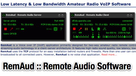 RemAud is a Voice over IP (VoIP) application primarily designed for two-way amateur radio remote control over the Internet. RemAud uses streaming-audio technology in a client-server architecture. It features high radio sound quality, low latency, low bandwidth and very low CPU usage by DF3CB