Search results
Query: Antenna
Links: 2503 | Categories: 254
This query is too generic. Please try adding an additional term to focus your research.
Categories
- Antennas > 20M > 20 meter Dipole Antennas
- Antennas > 20M > 20 meter Vertical Antennas
- Antennas > 20M > 20 meter Yagi antennas
- Antennas > 40M > 40 meter Delta Loop Antennas
- Antennas > 40M > 40 meter Dipole Antennas
- Antennas > 40M > 40 meter Loop Antennas
- Antennas > 40M > 40 meter Magnetic Loop Antennas
- Antennas > 40M > 40 meter Vertical Antennas
- Antennas > 40M > 40 meter Yagi Antennas
- Antennas > 6M > 6 meter J-Pole Antenna
- Antennas > 6M > 6 meter Moxon Antennas
- Antennas > 6M > 6 meter Yagi Antennas
- Manufacturers > Antennas > HF > Active antennas
- Software > Antenna analysis
- Manufacturers > Antenna Analyzers
- Radio Equipment > Antenna Analyzers
- Antennas > Antenna Books
- Antennas > Antenna Calculators
- Antennas > Theory > Antenna Gain
- Technical Reference > Antenna Launcher
- Manufacturers > Antenna Launcher
- Manufacturers > Antenna Masts and Mounts
- Shopping and Services > Antenna Mount
- Manufacturers > Antenna Parts
- Shopping and Services > Antenna Parts
- Technical Reference > Antenna Rotator
- Manufacturers > Antenna Rotators
- Software > Antenna rotor control
- Technical Reference > Antenna Switch
- Manufacturers > Antenna Switches
-
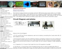 This homebrewed antenna tuning unit also incorporates a 50-ohm QRP dummy load, power meter (1 or 10 Watts full scale), and SWR meter
 -
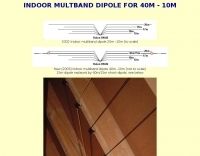 Indoor multiband dipole with EZNEC data files for simulation and analysis. Includes details on construction, tuning, SWR plots, and software usage. This page includes two different dipoles, a first version for 20-10 meters and an extended version covering 40-10 meters allowing a full coverage of most used ham radio HF Bands.
 -
 Multi-band centre-fed antenna capable of very efficient operation on all HF bands, specifically designed with dimensions which allow it to be installed in gardens and other open spaces which accommodate a reasonably-straight run of 31.1m (102 ft) for the flat-top standard model.
 -
 This resource details the construction and feeding of a vertical Moxon antenna specifically designed for the 20-meter band (14 MHz). It addresses the common issue of impedance variations at the feed point of vertical dipoles and Moxons, which typically requires the coax to exit at a specific angle (45-90 degrees) to maintain a good 50-ohm match. The presented solution involves opening the lower corner of the fed element and utilizing a transformer for impedance matching, simplifying installation and improving SWR. The alternative feeding method provides a stable match, eliminating the need for precise coax routing to achieve a low SWR. This design offers a practical improvement over conventional vertical Moxon feeding, making deployment significantly easier. The author, SM0DTK, confirms the efficacy of this setup, noting its fine performance and reduced installation complexity compared to traditional methods.
 -
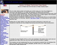 Build a 10 Meter Technician Class Dipole antenna. Get on 10 Meters fast with this basic 10 Meter Dipole project by hamuniverse
 -
 Article by DK5WL describes a multi-band DX antenna for the 160m-40m amateur radio bands with low visibility but great performance for long distance communication.
 -
 Vertical antennas for all HF bands, expecially 80 40 20 meters bands
 -
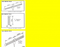 Drawings of shortened antenna for indoor usage, using short pvc tubes for 2 , 20 and 40 MHz by f1rfm
 -
-
-
 One common challenge in antenna systems is mitigating common-mode current on the feedline, which can distort radiation patterns and introduce RF in the shack. This project details a 1:1 balun design that ingeniously avoids traditional ferrite beads, often a costly component, by substituting them with steel wool. The steel wool, when integrated into the balun's construction, effectively attenuates unwanted RF on the outer braid of the coaxial cable, ensuring that the antenna radiates efficiently and as intended. The construction involves winding coaxial cable through a PVC former, with the steel wool strategically placed to provide the necessary common-mode impedance. This method offers a practical and economical alternative for hams looking to build effective baluns without the expense or availability issues associated with ferrite cores. The design principles focus on creating a balanced feed to the antenna, crucial for optimal performance of dipoles and other balanced radiators. Experimentation with such designs can lead to improved field results, particularly for those operating with limited budgets or seeking innovative solutions for their antenna systems. The simplicity of using readily available materials like steel wool makes this a compelling build for many radio amateurs.
 -
 A new tronics company, antenna maker, HF vertical antennas, vhf antennas, cb antennas
 -
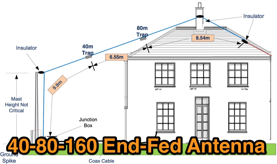 This PDF File desscribes how to homemade a multi-band end-fed trapped wire antenna resonating on the low bands of 160 80 and 40 meters. Contains trap design instructions and some construction tips.
 -
 Antenna modelling techniques and examples by W4RNL
 -
 This article addresses the subject of obtaining the best signal transfer from an antenna to the typical 50-ohm receiver input over a wide frequency range, with emphasis on medium-wave (500 - 2000 kHz), encompassing the standard AM broadcast band and the 160-m amateur band.
 -
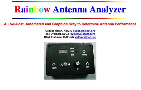 A small and inexpensive measurement device designed to determine antenna performance across the amateur bands through use of automatically collected SWR readings
 -
 Kioan's calculator for building a Cantenna , directional waveguide antenna for long-range Wi-Fi
 -
 Dipole, Yagi, Vertical, Cubic quad, Log periodic, J-pole, coil, and transmission line design package for the Macintosh
 -

-
 provides much greater flexibility in the construction, analysis, and interpretation of radiating structures using a rewritten NEC module.
 -
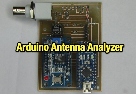 An home made antenna analyzer made with Arduino Nano
 -
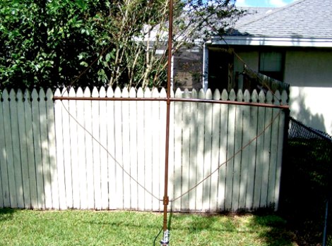 This document by W4HM explains the construction and usage of a 160 meter balanced coaxial receiving loop antenna, which can be easily adapted for the 40 and 80 meters bands. The content provides detailed instructions on building the antenna, its advantages, and how to optimize its performance for amateur radio operations. It is a valuable resource for radio amateurs looking to improve their receiving capabilities and enhance their overall radio communication experience.
 -
 A complete site for anyone wanting to use kites or balloons for supporting Top Band antenna systems.
 -
 This projects was developed as a result of experiments to become QRV on 80 meters, again, using the little balcony by SM0VPO
 -
 Perfect ground vs. poor ground. What is the difference? How does the ground influence the DX-gain?
 -
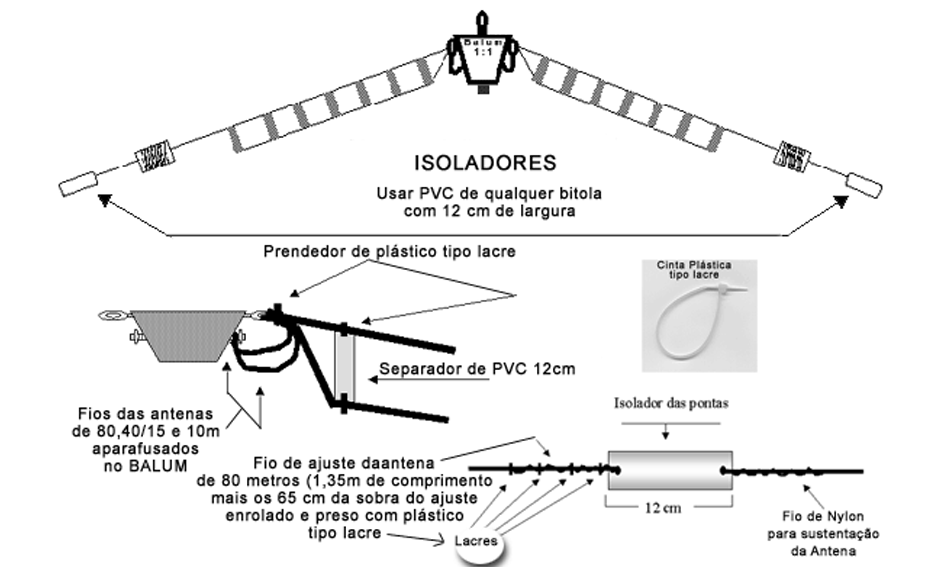 Wire antenna for 10-15-20-40-80 meters band, with many drawings and description in spanish
 -
 Examines the practical considerations and technical challenges of deploying mobile antennas for 10-meter operation, particularly for operators on the move. It addresses the inherently _lossy_ nature of shortened, loaded vertical antennas typically used in mobile configurations, encouraging hams to view these limitations as engineering challenges. The resource provides actionable advice on safeguarding vehicle electronics, selecting appropriate cabling like _RG-213_, and properly grounding antenna mounts to the vehicle chassis. Specific mounting strategies are detailed, including roof, trunk lip, and side-mounting for trucks and vans, along with their respective advantages and drawbacks. It emphasizes the importance of a robust ground plane and suggests methods for improving grounding beyond simple set screws. The article also touches on antenna choices, mentioning "bugcatchers" and "Hamstick types" as viable options for 10 meters. Furthermore, the guide transitions to stationary mobile operation, where antenna options expand significantly. It outlines how to deploy portable dipoles or 2-element beams from a parked vehicle, offering practical tips for assembly, storage, and mast guying using simple materials like a concrete block. It notes that a 5/8 wavelength height, approximately **20 feet** on 10 meters, often yields good short-skip and DX performance, even with a take-off angle above **20 degrees**.
 -
 A 10-meter J-Pole antenna, detailed in QST February 1950, offers a straightforward solution for hams operating with restricted space. This design, originally presented by W1BLR, is a **half-wave radiator** fed by a quarter-wave matching stub, providing a low-angle radiation pattern beneficial for DX. The article describes building the antenna from readily available materials like copper pipe, emphasizing its simplicity and effectiveness for **single-band operation**. The J-Pole's inherent design provides a good impedance match to 50-ohm coaxial cable without the need for an external tuner, a significant advantage for portable or minimalist stations. Its nondirectional pattern ensures coverage in all directions, making it a versatile choice for general operating on the 28 MHz band. The construction plans are clear, allowing even those with basic workshop skills to assemble a functional antenna.
 -
 A loopy loop loaded vertical antenna operating range 7.0 to 7.3 MHz by S. C. Chuck Smith, WA7RAI
 -
 The article details antenna tuning procedures, emphasizing SWR measurement and adjustment for both mobile and base station setups. It explains that SWR (Standing Wave Ratio) is the ratio of transmitted power to reflected power, with high SWR indicating poor impedance match and potential damage to a transceiver's final amplifier. Specific instructions are provided for CB antennas operating between 26-27 MHz, recommending initial SWR checks on channels 1, 20, and 40 to determine if the whip needs shortening or lengthening. Adjustments should be made in small increments, approximately 1/4 inch at a time, aiming for an SWR of 1.5:1 or better. For _Ham radio_ and other antennas, the same tuning principles apply, with a strong caution regarding RF energy exposure when operating at higher power levels. The resource suggests tuning base antennas at ground or roof level before final installation to simplify adjustments. It also advises rechecking SWR after final installation to confirm no changes occurred. The _Alpha Rubicon_ resource highlights the importance of a good ground plane for mobile antennas and proper coax routing to avoid pinching or proximity to electrical wires.
 -
 Design and build your own Hf thru Vhf antennas.Contains pictures, plans, parts list of very popular ham antennas along with experimental types.
 -
 Hammock 2 element wire Yagi antenna for 3 bands 20-15-10 based on VE7CA project
 -

-
 Review of the W5GI Multiband Mystery Antenna by July 2003 Issue of CQ Amateur Radio
 -
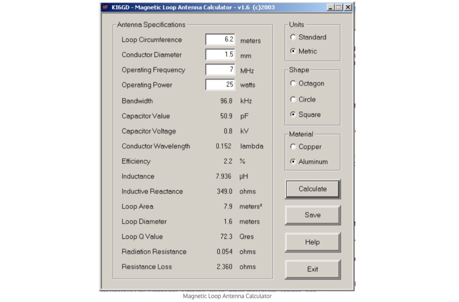 Free windows program to calculate magnetic loop antenna.This small loop antenna calculator allow to determine capacitance and voltage based on Loop circumference, desired resonant frequency, conductor diameter and the operating power
 -
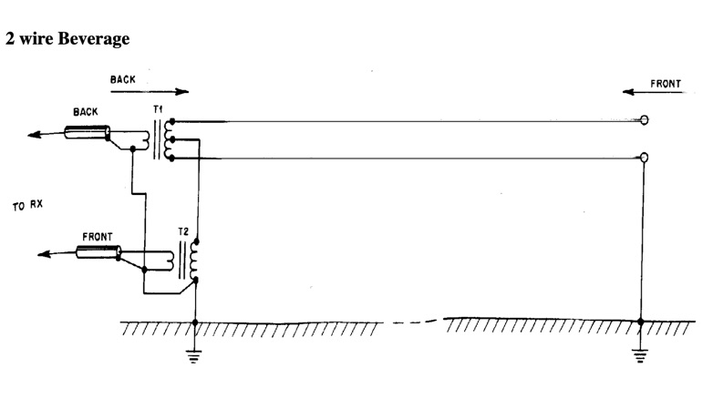 So you want to build a Beverage Antenna. This article offers insights on building a two-wire Beverage antenna for better reception. Key points include using long wire (at least a wavelength, ideally two), keeping it straight and away from vertical conductors, and sloping ends for noise reduction. The author recommends copper clad wire and mentions transformer design considerations for later discussion.
 -
 Inverted vee dipole antenna for 20 meters band by VK1OD
 -
 Calculations for determining the wind loading stress on an antenna mast. Link to a spreadsheet for calculating the mast bending stress based on wind speed and antenna cross sectional area.
 -
-
 A quick and easy to build loop antenna for shortwave listeining can tune from 5 to 18 Mhz
 -
 All copper J-Pole antennas for sale. 6 meter, 2 meter, 222 MHz, 440 MHz, LPFM, Marine, GMRS. Includes a construction plan in pdf format if you wish to build your own antenna.
 -
 802.11b WLAN Waveguide Antennas Unidirectional & Omnidirectional. High gain, Simple construction by Trevor Marshall
 -
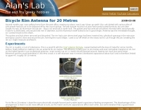 A small transmitting loop antenna for 20 metres using a aluminium bicycle wheel rim.
 -
 The document is a PDF detailing the construction of the DBJ-1 VHF-UHF Dual Band J-Pole antenna for amateur radio use. It provides instructions on how to build a high-performance dual band base antenna for VHF and UHF bands using a single feed line for less than $10.
 -
 Presents a practical approach to constructing a portable, lightweight antenna support structure, ideal for field operations or temporary installations. The design utilizes readily available PVC pipe sections, allowing for a total height of **20 feet** and a transportable weight of **25 lbs**. Detailed material lists specify various PVC pipe diameters and lengths, along with couplers, tees, and elbows, facilitating a modular assembly that can be easily disassembled for transport. Accompanying the tower design, the resource also outlines the construction of a _MicroVert_ antenna, including formulas for radiator length, capacitance, and inductance. It provides guidance on creating a current balun using ferrite beads or a coax coil, and calculating counterpoise length for optimal performance. The antenna section includes a schematic diagram illustrating the connection of the SO-239 connector and counterpoise.
 -
 Calculating and building an Eggbeater antenna. InstantTune and push-button Rx. Documentation available in french and english
 -
 The ZS6BKW multiband HF antenna, a design by ZS6BKW (G0GSF), functions effectively on multiple HF bands without requiring an Antenna Tuning Unit (ATU) for 40, 20, 17, 12, 10, and 6 meters. This antenna, approximately **27.51 meters** (90 feet) long with a 12.2-meter (40-foot) open-wire feeder, is a direct descendant of the _G5RV_ but offers superior multi-band resonance. It can be deployed as a horizontal dipole or an inverted-vee, with the latter requiring only a single support and maintaining an apex angle of at least 90 degrees to prevent signal cancellation. Performance data, recorded with an MFJ Antenna Analyser, indicates SWR values of 1:1 on 7.00 MHz (40m) and 14.06 MHz (20m), with SWR below 1.3:1 on 17m, 10m, and 6m. While primarily designed for these bands, the antenna can be adapted for 80m, 30m, and 15m with an ATU, preferably at the balanced feeder's base. The use of 450-ohm twin-lead for the feeder is recommended over 300-ohm for improved strength and reduced losses, especially in adverse weather conditions. This design, originally published in _RadCom_ in 1993 and featured in Pat Hawker’s "Antenna Topics," provides a compact and efficient solution for HF operation, particularly for those with limited space or resources.
 -
 For amateur radio operators seeking a compact, directional antenna for the 10-meter band, this resource details the construction of a Moxon Yagi beam. The design utilizes readily available PVC pipe for the boom and elements, with specific measurements derived from the Moxon Rectangle Generator software. It outlines the assembly process for the main boom and end sections, providing critical dimensions for element spacing and overall length to achieve resonance at 28 MHz. The Moxon configuration offers a smaller footprint compared to a traditional Yagi, making it suitable for limited space installations. The article provides practical guidance for hams interested in a DIY antenna project, emphasizing the use of common hardware store materials. It specifies a 1 1/4" PVC schedule 40 pipe for the main boom and details the use of tees, reducing bushings, and 45-degree elbows for the element ends. Key measurements like the 55" spacing for the ends and the 150 3/4" overall length are provided, enabling replication of the design. The Moxon's inherent wide beamwidth and good front-to-back ratio make it an effective choice for DXing on 10 meters.
 -
 The G3TPW Cobwebb antenna covers five bands, 14 - 28 mhz, including the WARC bands
 -
 Presents the design and construction details for a VHF bicycle-mobile antenna, originally published in QST. The antenna utilizes a modified _Arrow J-Pole_ design, adapted for portable operation on a bicycle frame. Performance characteristics include a reported **1.5:1 SWR** across the 2-meter band, demonstrating effective impedance matching for typical handheld transceivers. Construction involves readily available materials, emphasizing lightweight components suitable for mobile deployment. The document provides a parts list and step-by-step assembly instructions, detailing the radiator and ground plane element lengths for optimal resonance at 146 MHz. Mechanical considerations for mounting on a bicycle are also addressed. The resource covers practical aspects of integrating the antenna with a bicycle, including cable routing and securing methods. It offers insights into achieving reliable VHF communications while operating in a mobile, low-power environment, making it relevant for field day activities or casual portable operation.