Build Your Own Maria Maluca Multiband HF Antenna
Find schematics, dimensions, and technical guidelines for constructing this popular two-element beam antenna for various HF bands.
The Maria Maluca antenna is a classic multiband HF beam, often built as a two-element array. Originally designed in the 1950s, it allows operators to achieve directivity and gain across several amateur radio bands, typically from 40 to 10 meters, without needing multiple antennas or complex switching. Its design often involves a driven element and a parasitic element that can function as either a director or reflector, depending on the band and tuning.
Hams interested in building a Maria Maluca can find various construction guides and technical diagrams. Resources often detail the specific dimensions for elements and the use of ribbon line for feeding, as shown in designs by DL7JV and PY2BBP. These projects provide practical insights into optimizing element spacing and lengths for different bands, helping operators achieve good forward gain and front-to-back ratios for DX work.
-
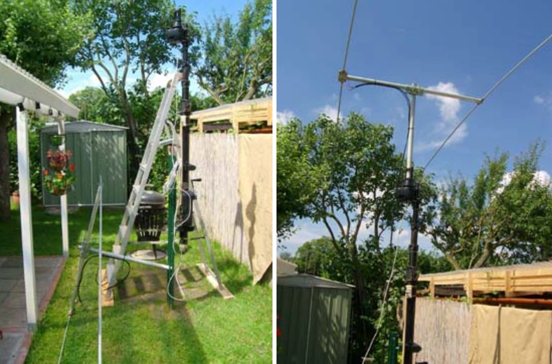 Horizontal HF 6-Band turning arranging emitter with 2 elements Maria Maluca
 -
 An antenna originally planned in the sixties, a two element beam antenna tunable on several band, in french
 -
 Construction details for the "Maria Maluca" antenna by DL8NCR, a compact 6-band HF/6m directional beam using ribbon line feed.
 -
 A two elements beam antenna tunable from 6 to 20 meters, based on the Maria Maluca antenna project by DB9EX, in german
 -
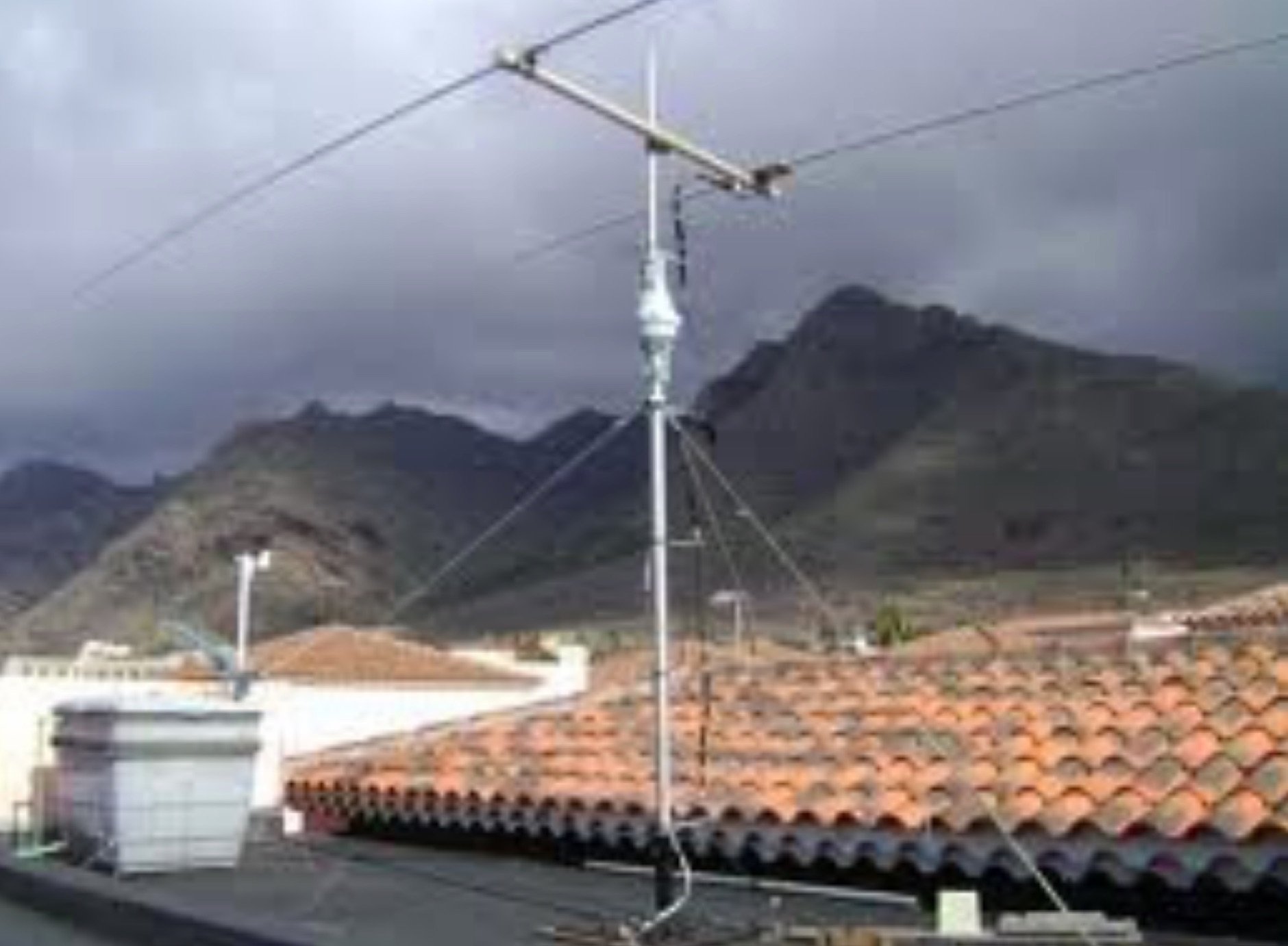 The Maria Maluca HF multiband antenna as designed in 1957 by PY2BBP is a directive antenna for 15 meter and a passive element that works as director and reflector in different bands
 -
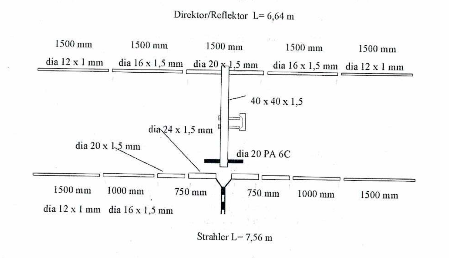 A PDF File of a Maria Maluca multiband HF antenna with schematic diagram, dimension and plan