Antenna Theory: Principles of Radio Wave Propagation
Understand fundamental antenna concepts, radiation patterns, impedance matching, and transmission line behavior for effective radio communication.
Understanding antenna theory is fundamental for every ham radio operator, whether building a simple dipole or designing complex arrays for DX. It covers the principles of how antennas radiate and receive radio waves, how they interact with the surrounding environment, and how feedlines transfer RF energy. A solid grasp of these concepts helps hams optimize their stations for better signal reports and more reliable QSOs across all bands.
This category provides essential insights into antenna behavior, from basic concepts for beginners to advanced topics for experienced builders. Operators can learn about radiation patterns, the impact of current distribution on array performance, and the physics behind ground systems for vertical antennas. Resources also cover practical aspects like optimizing inductors for loading coils and using tools such as the Smith Chart to analyze transmission lines and impedance matching.
Subcategories
- Antenna Gain (17)
- Impedance matching (21)
- Wind Load (2)
-
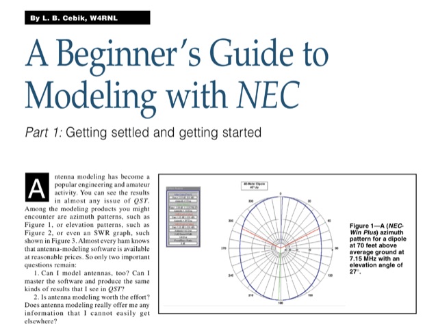 Antenna modeling is an essential technique for both amateur and professional engineers, enabling precise analysis of antenna performance. This guide, published on 4 different QST articles by L. B. Cebik, introduces NEC-2, a widely used public domain software for modeling antennas, focusing on its capabilities and practical applications. The series aims to demystify the modeling process, providing foundational knowledge and techniques for effective antenna design. Key concepts include understanding the method of moments and the importance of segmenting antenna elements. By mastering these principles, users can enhance their comprehension of antenna behavior and optimize their designs for improved performance.
 -
 The Smith Chart, named after its inventor Phillip H. Smith, is a graphic tool used to solve transmission line problems in the field of ham radio operations. By using the Smith Chart, ham radio operators can determine the feed point impedance of an antenna, design impedance-matching networks, and optimize power transfer between a source and its load. The chart consists of resistance and reactance circles, providing a visual representation of complex mathematical relationships related to transmission line operations. Understanding and utilizing the Smith Chart is essential for hams looking to enhance the performance of their RF circuitry.
 -
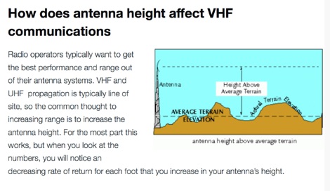 How to calculate range for a VHF antenna with a simple formula and how to increase VHF coverage.
 -
 Wondering whether human body could be used as an antenna.
 -
 How to improve your transmitting antennas for very low solar activity periods, vertically polarized 160 meter antennas, horizontally polarized 80 to 10 meter antennas, single or stacked yagis, multi-tower stations
 -
 The following is the third part of a three-part guide to help get started with HF, written by Charlie Davy – M0PZT
 -
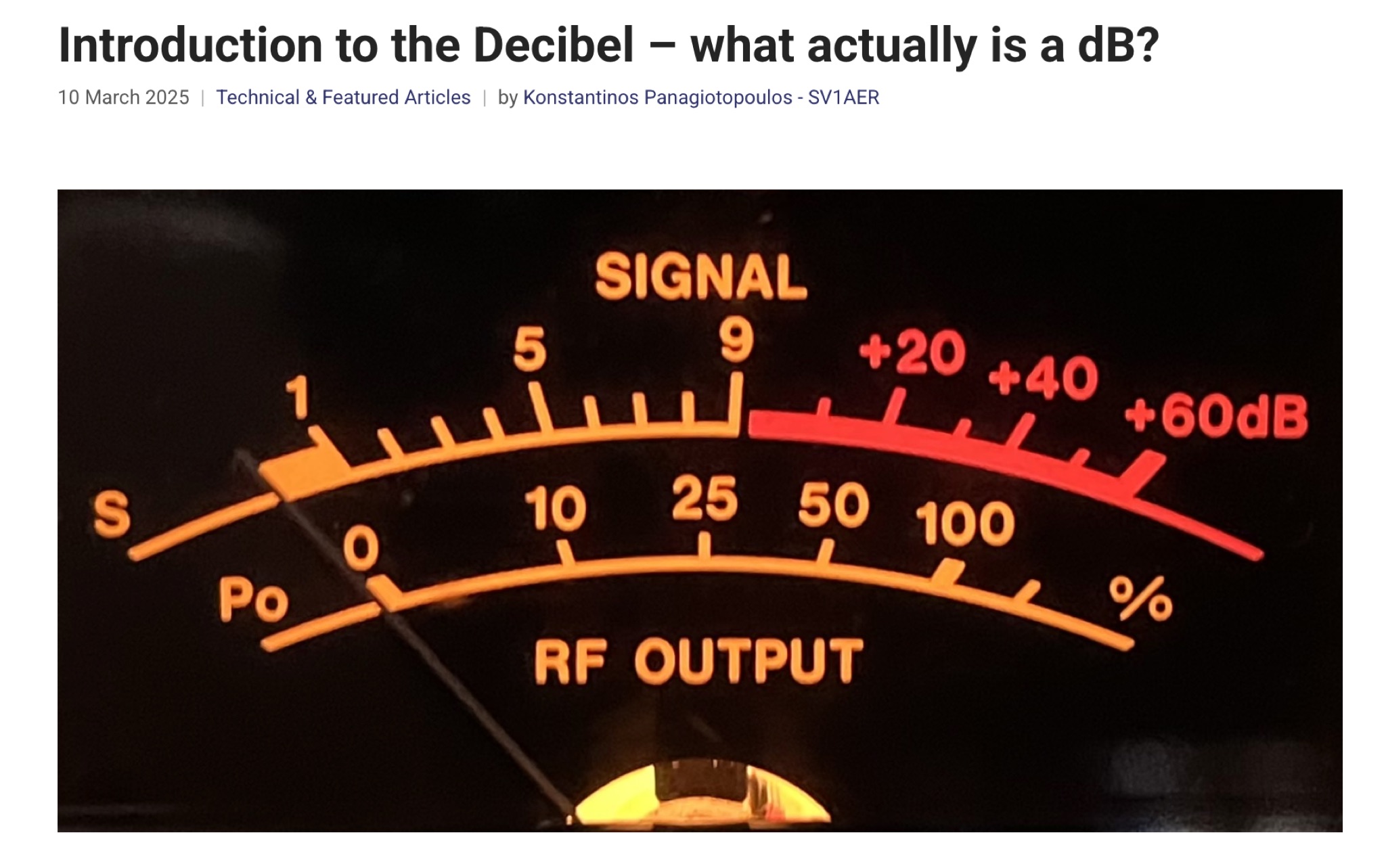 This article provides a comprehensive introduction to the decibel (dB), its logarithmic nature, and its applications in power, voltage, and antenna gain calculations. It explains how dB simplifies comparisons in electronics, telecommunications, and audio perception. The author clarifies key mathematical concepts, including power ratios, voltage doubling, and absolute levels like dBm and dBV. The discussion on S-units and antenna system gain is particularly relevant for radio amateurs. Overall, this is an informative and well-structured guide to understanding and applying decibels in technical fields.
 -
 This article focus on the radiation angle of vertical antennas and the fundamentals of electromagnetic wave propagation. The calculation of antenna length at 145 MHz is followed by an explanation of electromagnetic wave speed and the link between wavelength, frequency, and velocity. Author discusses the 5/8th wave vertical antenna, namely its performance and the influence of radiation angle on signal transmission. Figures and analogies demonstrate how different antenna types produce distinct radiation patterns. This highlights the importance of selecting the right antenna for a certain purpose, such as local traffic or dxing. The article discusses a variety of factors that affect antenna performance, including SWR, propagation conditions, and equipment dependability
 -
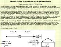 Phased Spaced Active Whips and Broadband Loops by WA1ION
 -
 Presentation about Practical Antenna Modeling Using the NEC Codes with examples of HF wire antennas and 4NEC2. How to define and edit the models, Running the simulations, Work some examples, Variables usage, Deal with Feed Lines and ground
 -
 This paper by Leif Asbrink (SM 5 BSZ) presents a practical approach to designing very high gain Yagi antennas, focusing on the "brute force" optimization method. The method, described in a previous article, ensures convergence independent of initial guesses. The paper provides detailed tables of element lengths and positions for Yagi antennas optimized for 144.1 MHz with a 50-ohm feed point impedance, aiming for minimal losses and high accuracy in comparisons.
 -
 Coax Velocity Factor in Baluns, Does it Matter? Test results show coaxial cable velocity factor does not always enter into stub length calculations especially in the world of Baluns
 -
 The video showcases the setup of a 300 MHz oscillator, a 100W radiofrequency amplifier, and a dipole antenna for transmitting radio waves, leading to the fluorescence of a nearby light bulb. It demonstrates the presence of standing waves on the dipole antenna and how intensity varies along its length. Additionally, the usage of a copper pipe as a receiving antenna is explored, showing changes in intensity depending on alignment and proximity to the transmitter. Finally, a B field antenna sensitive to magnetic fields is introduced, revealing brightness variations in different orientations. The video offers insightful observations on radio wave transmission and reception phenomena.
 -
 W5ALT Antenna notes for a dummy dedicated to restricted space antennas
 -
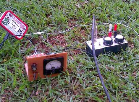 RF Current measurements on a Long Wire W3EDP antenna
 -
 Smart antennas or the adaptive antenna array and smart antenna technology used with SDR, cognitive radio, MIMO, and other new technologies.
 -
 How to stack different band yagi antenna in a single tower
 -
 This is a synopsis of a talk presented to the Sydney VHF DX GROUP by VK2ZAB on how, when and why is convenient to build a Yagi antenna stack.
 -
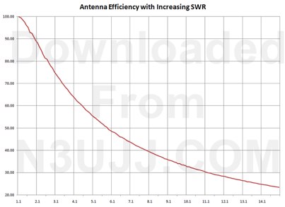 How is your SWR - determine the power loss to expect for a given SWR, includes an excel spreadsheet by n3ujj
 -
 This is a QST Article published in January 1982 by W1FB D. Demaw and HH Beverage and is a complete review of the original article published in 1922, which updates and reivew the beverage antenna theory and developlment, explaining the antenna design of transformers and gives accurate reports on antenna general performance.
 -
 A half wave wire that is tuned for resonance on 80m will NOT be resonant on 40m despite a precise harmonic relationship between the two bands. The End Effect is caused by a capacitive coupling between an unterminated wire end and the ground.
 -
 This article published on QEX details measurements of tree conductivity and permittivity at HF frequencies, addressing a long-debated topic in amateur radio. N6LF conducted experimental impedance measurements on Douglas fir and maple trees using a vector network analyzer with rings of nails inserted into tree trunks. Results showed that tree conductivity increases with frequency while relative permittivity decreases, similar to soil characteristics. Measured conductivity ranged from 0.06 to 0.4 S/m at 10 MHz, aligning with values used in previous research. These findings validate that NEC modeling can reliably estimate trees' substantial impact on HF antenna performance.
 -
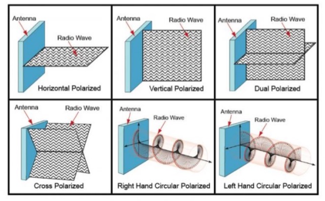 What is antenna polarization, and why does it matter. Horizontal versus Vertical versus Circular polarization. Undestanding how antennas perform better with different polarizations.
 -
 This article explores the powerful features of AutoEZ as an Excel application working with EZNEC antenna modeling software. The article demonstrates how variables, equations, and formulas enable versatile antenna design and automatic optimization. Through practical examples including dipoles, inverted vees, delta loops, and monopoles, the author shows techniques for achieving resonance, implementing transmission line resonators for broadbanding, and optimizing antennas across frequency ranges. The step-by-step demonstrations cover unit conversion, coordinate calculations, segmentation considerations, and SWR optimization. This practical guide illustrates how AutoEZ extends EZNEC's capabilities, making complex antenna modeling more efficient and accessible.
 -
 G0KYA MMANA-GAL presentation and samples
 -
 Antenna patterns are all about interference. Presentation on wire antennas for HF bands. Dipoles, horizontal and vertical dipoles, effects of ground on radiation patterns, multi-band wires antennas. Knowing what you should expect from the radiation patterns for waves on your wires will help you choose what will work best for your needs. The principles of interference can lend insight into what to expect from a wire antenna.
 -
 Mounting antenna close each other. Distance calculations and tips on setting up antennas by KB9VBR
 -
 Many antennas and antenna designers neglect the true cause of loss. The major problem using short antennas is the reactance, not the length
 -
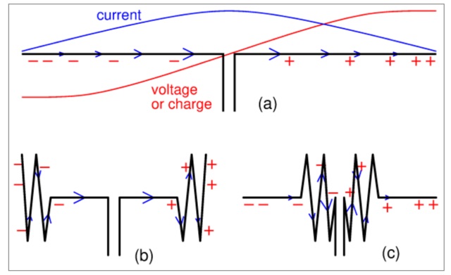 The title may seem a strange question. Still, it is often said that the part where the current is largest, radiates most. And from that a rule of thumb follows, saying that if you don't have enough space to hang a complete half-wave wire dipole then try to make the central part hang as freely as possible.
 -
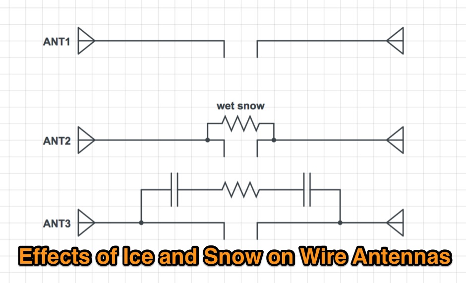 Effects of ice an snow in a wire dipole antennas
 -
 K2KW notes on verticals antennas
 -
 Experimenting OCF and dipole wire antennas over house roof. Effects of roofs on wire antennas
 -
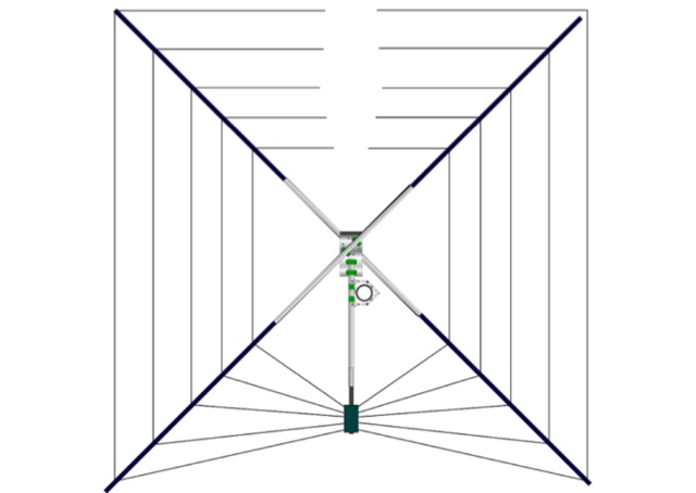
 A selection of technical articles and analysis offering guidance and insight to enable you to recognise and build your own high performance yagi design.
 -
 Learn about the practical design and construction of Yagi antennas for ham radio operators. This post explores the benefits of Yagi antennas in receiving and transmitting RF signals, concentrating signal energy in one direction for long-distance communication. Discover the theory behind Yagi antennae, the importance of element size and spacing, and the resources available for sizing and construction. Whether you're interested in OTA television or amateur radio communication, understanding Yagi antenna design can enhance your signal reception and transmission capabilities.